Note:
The console port of S5612 does not support traffic control. Therefore, you must set the
option
data traffic control
to
none
when you configure the switch with the super
terminal. Otherwise, the single-pass problem will arise on the super terminal.
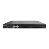
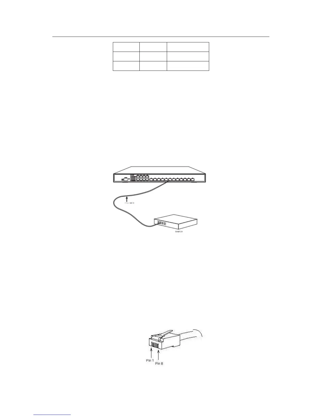
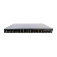
3.3.2 Connecting 10G Ethernet SFP+ Ports
The S5612 switch has 12 10G SFP+ ports. Each port has its corresponding indicator:
TE1~TE12. You can connect the SFP+ optical module to the SFP+ port and then you
can connect other Ethernet terminal devices through the optical cable.
Figure 3-6 Connecting the 10G SFP+ port and other Ethernet terminals
Caution:
The switch shown in figure 3-6 does not represent the material S5612.
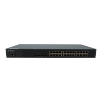
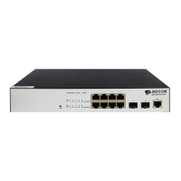
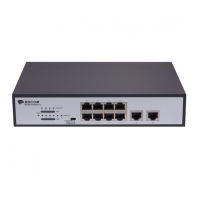
3.3.3 Connecting Gigabit Ethernet TX Ports
S5612 provides 8 10/100/1000Base-T ports. Each port has its corresponding
indicator:1-8. The indicators are used to indicate the LINK/ACT state. The ports can
connect other Ethernet terminal devices through the UTP port and the direct-through or
cross network cable. The numbering order of the pins in the UTP port is the same as
that in the console port. See figure 3-6.