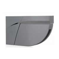
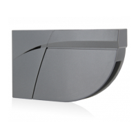
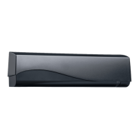
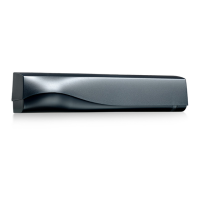
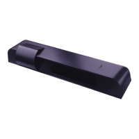
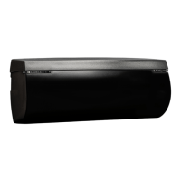
The LZR®-FLATSCAN 3D SW and LZR®-FLATSCAN SW are safety sensors for automatic swing doors, utilizing laser technology to secure both the moving door wing and the hinge area. To achieve this, a module must be installed in the upper corner of the door wing on both sides of the door. The FLATSCAN 3D SW can be paired with another FLATSCAN 3D SW or a FLATSCAN SW. When used in combination with a FLATSCAN SW, the FLATSCAN 3D SW must be connected to the door controller to access all features, such as opening functions.
Function Description:
The LZR®-FLATSCAN 3D SW and LZR®-FLATSCAN SW are laser scanners using time-of-flight measurement for presence detection. They provide safety for automatic swing doors by creating detection fields that monitor the door wing and hinge area. The FLATSCAN 3D SW offers a door wing safety field of 80° and a hinge zone safety field of 20°. The FLATSCAN SW provides a door wing safety field of 90° and a hinge zone safety field of 16°. Both sensors offer an "Uncovered Zone" feature, adjustable by remote control, with a factory value of 10 cm, which can be increased in case of snow, dead leaves, etc.
The FLATSCAN 3D SW provides an edge zone safeguarding the leading edge of the door leaf while the door is closing. This edge zone is activated when the door leaf is almost closed and aims to increase the protection of hands and fingers. The edge zone must be adjusted according to the door type (single or double leaf). For the edge zone to be fully operational, relay 3 (OPEN) must be connected to the door controller.
The FLATSCAN 3D SW also supports "Virtual Opening Buttons," allowing up to two virtual buttons to be added in the second curtain. These can be used as activation zones to open the door manually and can be placed outside of the safety zones. To operate this feature, the FLATSCAN 3D SW must be connected to the door controller with the provided 10-strand cable.
Operating Modes:
The sensors offer three operating modes:
- AUTO: In this mode, the Flatscan operates dynamically. When using two interconnected modules, it operates in dynamic mode. With a single module, it operates in static mode. In dynamic operation, the Flatscan dynamically adapts its detection fields according to the door position, allowing for an expanded field and wall masking. In static operation, the detection field remains unchanged regardless of the door position. If opening against a wall, the door controller must be set accordingly to ignore it.
- STATIC: This mode forces static operation.
- MAN. (Manual): This mode is used for manually operated automatic doors. The Flatscan operates in dynamic operation, and the reopening and opening signals are set on the hinge zone while the door is closing. Two modules must be interconnected to use this mode.
Important Technical Specifications:
- Detection Mode: Presence
- Max. Detection Range: 4 m (diagonal) with 2% reflectivity (e.g., at W = 1.5m -> max. H = 3.7 m) for both models.
- Field of View:
- FLATSCAN 3D SW: Door wing safety: 80° / Hinge zone safety: 20°
- FLATSCAN SW: Door wing safety: 90° / Hinge zone safety: 16°
- Resolution:
- FLATSCAN 3D SW: Curtain 1: 500 spots (0.2° between spots), Curtain 2: 100 spots (1° between spots), Curtain 3: 60 spots (1.7° between spots), Curtain 4: 40 spots (2.5° between spots)
- FLATSCAN SW: Door wing safety: 70 spots (1.3° between spots), Hinge zone safety: 100 spots (0.2° between spots)
- Typ. Min. Object Size:
- FLATSCAN 3D SW: 2cm @4m in curtain C1
- FLATSCAN SW: Door wing safety: 10 cm @ 4m (in proportion to object distance, DIP 2 = ON), Hinge zone safety: 2 cm @ 4m (in proportion to object distance, DIP 2 = ON)
- Testbody: 700 mm x 300 mm x 200 mm (testbody CA according to EN 16005 & DIN 18650) for both models.
- Optical Characteristics (IEC/EN 60825-1:2014): IR LASER: wavelength 905 nm; output power < 0.1mW; Class 1 for both models.
- Supply Voltage: 12-24 V DC ± 15 % for both models.
- Power Consumption: < 2 W for FLATSCAN 3D SW, ≤ 2 W for FLATSCAN SW.
- Response Time:
- FLATSCAN 3D SW: Typ. <120 ms / Max. 220 ms (curtain 2)
- FLATSCAN SW: Door wing safety: max. 50 ms / Hinge zone safety: max. 90 ms
- Output:
- FLATSCAN 3D SW: 3 electronic relays (galvanic isolation - polarity free), 42V DC/AC peak, 100 mA
- FLATSCAN SW: 2 electronic relays (galvanic isolation - polarity free), 42V DC/AC peak, 100 mA
- LED-signals:
- FLATSCAN 3D SW: 1 RGB LED: detection/output status
- FLATSCAN SW: 1 bi-coloured LED: detection/output status
- Dimensions:
- FLATSCAN 3D SW: 145 mm (L) x 88 mm (H) x 60 mm (D) (mounting base + 7 mm)
- FLATSCAN SW: 142 mm (L) x 85 mm (H) × 33 mm (D) (mounting base + 7 mm)
- Material - Colour: PC/ASA - Black - Aluminum - White for both models.
- Tilt Angles: FLATSCAN 3D SW: 0° to +5°, FLATSCAN SW: +2° to +10°.
- Protection Degree: FLATSCAN 3D SW: IP44 (IEC/EN 60529), FLATSCAN SW: IP54 (IEC/EN 60529).
- Temperature Range: FLATSCAN 3D SW: -25°C to +60°C, FLATSCAN SW: -30°C to +60°C if powered.
- Humidity: 0-95% non-condensing for both models.
- Vibrations: < 2 G for both models.
- Min. Door Wing Speed: 2°/sec for both models.
- Conformity: EN 12978; EN ISO 13849-1 Pl "d"/ CAT2; EN 62061 SIL 2; DIN 18650-1 (testbody CA); EN 16005 (testbody CA) for both models.
Usage Features:
- Installation Tips: Avoid vibrations, do not cover the laser window, avoid moving objects and light sources in the detection field, avoid the presence of smoke and fog, avoid condensation, and avoid exposure to sudden and extreme temperature changes. Keep the sensor permanently powered in environments where the temperature can descend below -10°C.
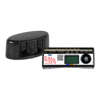
- Mounting: The base slides off the sensor module and is positioned on the door frame using positioning aids for correct alignment. Ensure the sensor does not hinder door movement. Holes are marked and pre-drilled. Positioning aids are removed from the base, and the base is firmly fastened with screws. A 10 mm hole is drilled through the bases and the door for the MAIN-SECONDARY cable, with edges softened. The MAIN-SECONDARY cable is passed through the hole and positioned firmly in the notch of the base. The sensor is then fastened to the base, and the black plug is connected to the black connector, ensuring wires are tucked away. The lock screw is fastened firmly. If a sensor is not connected to the door controller, it is closed using a plug (SECONDARY module).
- Wiring to Door Controller: For MAIN modules (connected to the door controller), the flexible tube length is determined, surplus cut, and the power cable passed through it. The white plug connects to the white connector. A loop is made with the power cable wires and passed through a notch, using the other part of the cable to block the wires. A clamp fixes the flexible tube to the sensor, and two screws are fastened. The other side of the flexible tube is tightened using a cable cap, and the power cable is routed to the door controller.
- DIP Switch Settings: DIP switches allow configuration of parameters like environment (standard/critical), background (on/off), and hinge zone (on/off). After changing a DIP switch, the orange LED flashes. A long push on the push button confirms settings, followed by green flashes indicating the number of connected modules.
- Remote Control Settings: Remote control allows adjustment of dimensions for hinge zone, edge zone, door zone, and height of all zones. It also allows configuration of output parameters (R1, R2, R3), uncovered zone, antimasking/background settings, safety field depth, and opening field.
- Teach-in Procedure: Before a teach-in, ensure glass surfaces are covered, the door controller is set up, the door is closed, all relay outputs are connected, the MAIN-SECONDARY cable is connected, the detection field is clear, and the laser window protection is removed. A brief push on the MAIN module's button starts the teach-in. The LED flashes red-green. For double swing doors, repeat on the other MAIN module. Wait for all main modules to flash green. Position yourself in front of the door and make up-and-down movements at closing edge level to mark detection zone limits. The LED flashes red during calculation. Once all main modules flash green again, the Flatscan 3D SW opens the door to learn the environment. Ensure you are outside the detection field (min. 2 m). During door closing, the sensor flashes red. The teach-in is complete when the door is fully closed and the LED is off. A new teach-in is required if the sensor tilt angle or objects in the detection zone change.
- Testing and Adjusting: Check safety field positioning by placing an object in the detection field. Adjust the tilt angle of the laser curtain (0° to 5° for 3D SW, +2° to +10° for SW) using the adjustment screw if necessary. After any angle change, sensor repositioning, or environment change, a new teach-in and field test are required.
- Service Mode: The service mode deactivates door safety for 15 minutes, useful for installation, mechanical teach-in, or maintenance. Enter by pushing the button for > 3 seconds (LED turns off). Exit by pushing again for > 3 seconds. It deactivates automatically when launching a teach-in.
- Remote Control Usage: The remote control allows unlocking the sensor for adjustments. If the red LED flashes quickly after unlocking, an access code (1-4 digits) is required. If the code is unknown, cut and restore power for 1 minute to access the sensor without a code. A different access code for each module is recommended to avoid changing settings on both simultaneously. The remote control can save/delete access codes, adjust parameters, check values (number of flashes indicates parameter value), and restore factory values (all values or all except field dimensions and output configurations).
Maintenance Features:
- Cleaning: Clean the laser window with compressed air. If needed, wipe only with a soft, clean, and damp microfibre cloth. Do not use dry or dirty towels or aggressive products, and avoid direct exposure to high-pressure cleaning.
- Troubleshooting: If the door reacts unexpectedly, activate service mode (no safety) and launch a door cycle to determine if the sensor, door controller, or a radar sensor is the cause. Maintain a minimum distance of 15 cm between FLATSCAN modules and radar sensors or use the LZR®-FLATSCAN Protective cover.
- LED Indicators: The RGB/bi-colored LED provides status information. Different flash patterns indicate various issues like bad teach-in, unwanted detections, inverted power supply, faulty cable/sensor, test error, opening function deactivation, remote control issues, memory problems, DIP-switch confirmation, internal faults, power supply issues, high internal temperature, communication errors, background detection issues, masking elements, teach-in errors, and faulty measurements of door position. The manual provides specific actions for each LED indication.
- Warranty: The warranty is invalid if unauthorized repairs are made or attempted by unauthorized personnel.