1. HARDWARE INSTALLATION
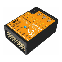
You can position MICROBEAST PLUS flat or upright on the helicopter. The large socket must point to the front or to the rear of
the helicopter. The small white socket must be aligned with the longitudinal axis.
The sensor axis (housing edges of the device) must be aligned exactly parallel to all three rotation axis of the helicopter.
However, it is allowed to position the device offset from the rotation axis.
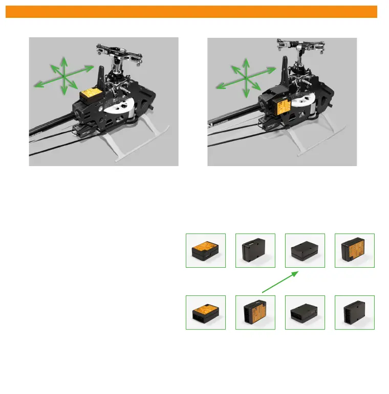
In summary there are 8 mounting orientations possible:
1. flat, sticker on top, socket pointing to front
2. upright, button up, socket pointing to front
3. flat, sticker showing to ground, socket pointing to front
4. upright, button down, socket pointing to front
5. flat, sticker on top, socket pointing to rear
6. upright, button up, socket pointing to rear
7. flat, sticker showing to ground, socket pointing to rear
8. upright, button down, socket pointing to rear
Use one of the supplied 3M gyro pads to stick the device to your helicopter. The device housing must not directly touch
the chassis of the helicopter. When connecting and laying out the servo and receiver wiring later onwards please make sure
the wires do not pass tension to the MICROBEAST PLUS. It is not recommended to bundle or tie down the leads close to the
MICROBEAST PLUS device.
1. 2. 3. 4.
5. 6. 7. 8.
F
l
i
g
h
t
d
i
r
e
c
t
i
o
n