Do you have a question about the Becker BDC-i440 Series and is the answer not in the manual?
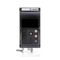
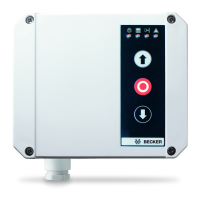
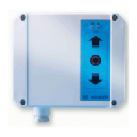
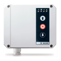
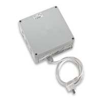
Identifies the BDC-i440 door control unit and its version.
Provides important information for fitters, electricians, and users.
Explains the meaning of symbols and pictograms used in the manual.
Details warranty terms and manufacturer liability for product use.
Covers applicable regulations and requirements for qualified technicians.
Highlights cautions, attention notes, and critical operating notes.
Specifies permitted applications and restrictions for the control unit.
Provides the physical dimensions of the control unit.
Details the process for attaching and removing mounting brackets.
Covers installing the unit on a wall and handling the cover.
Details safety precautions for performing electrical connections.
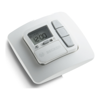
Describes the operation of buttons and the rotary-push button.
Explains the different operating levels and their purposes.
Details using the status level and interpreting error messages.
Describes accessing and using the operator level for basic functions.
Explains accessing technician level and changing parameters.
Details technician level access, password entry, and parameter selection.
Outlines the steps to open the parameterization level and edit parameters.
Explains mechanical limit switches (MLS) and absolute value encoders (AE).
Guides through first-time setup, profile, and safety edge selection.
Verifies the correct drive rotation direction of the door.
Details programming limit positions for absolute value encoders.
Covers E-stop, electric, pressure-wave, OSE, PNP/NPN safety devices.
Describes connections for various safety devices.
Explains SE1/SE2 settings and input profiles.
Details SE2 parameters, FE input functions, and assignments.
Lists available output functions and their values.
Explains testing methods for safety devices using output relays.
Details functions like door position, motion, lights, and locking.
Describes the M1 expansion board and loop detector module.
Describes the M2 expansion board and its inputs/outputs.
Covers installation of the safety radio receiver PCB and basic function.
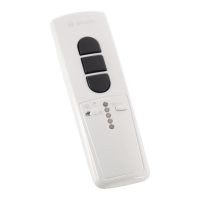
Explains 1-channel and 4-channel receivers and their button functions.
Describes programming and clearing transmitter codes for radio receivers.
Explains selecting door profiles for different limit switch types.
Lists parameters that can be set by the operator.
Lists parameters that can be set by technicians.
Provides detailed descriptions for technician-settable parameters.
Explains various status messages and symbols on the display.
Shows status messages during calibration and dead-man operation.
Details diagnostic inputs and classifies error message types.
Details fatal, minor, informational, and system error codes and remedies.
Shows circuit diagrams for OSE, electric, pneumatic safety edges, PNP/NPN outputs.
Details circuit diagrams for various light barrier configurations.
Shows circuit diagrams for pull-in safety devices and wicket door switches.
| Brand | Becker |
|---|---|
| Model | BDC-i440 Series |
| Category | Control Unit |
| Language | English |