Do you have a question about the Becker BDC-i440R and is the answer not in the manual?
Explains symbols used in the manual for caution, attention, and information.
Details conditions and limitations regarding product warranty and user responsibilities.
Provides essential safety guidelines, standards, and technician qualifications for installation and maintenance.
Offers critical advice on safe operation, child safety, equipment care, and avoiding hazards.
Outlines essential checks and procedures for initial setup and parameter configuration by trained personnel.
Guides on attaching and removing the control unit's fastening brackets for mounting.
Illustrates wall mounting and safe handling of the control unit cover during installation.
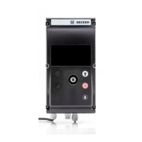
Explains DDT operation for parameterization, diagnostics, and input commands.
Describes the optional emergency stop button and main switch for power disconnection and safety.
Details status level navigation, parameter access, and error message display and prioritization.
Explains how to view door status, counters, safety edges, and function inputs via the unit.
Outlines operations and information accessible in the operator level, such as changing running times and viewing counters.
Details the process for accessing and performing parameterization in the technician level using password protection.
Provides instructions on editing parameters and properly exiting operator and technician modes.
Instructions on how to verify and adjust the door's running direction for correct operation.
Explains that limit positions are set via external switches and are not reparameterized by the unit.
Details the procedure for setting door limit positions using an absolute value encoder, including safety edge connection.
Describes the connection and function of emergency stop buttons and general safety devices.
Details various safety edge types and their connection requirements, plus other safety devices.
Lists output functions, their values, and procedures for external testing of safety functions.
Details specific output functions like door position, motion, lights, and locking mechanisms.
Combines status codes, calibration messages, dead-man messages, and diagnostic inputs.
Classifies errors by type, lists codes, and provides basic troubleshooting guidance.
States the control unit is maintenance-free and advises on exterior cleaning.
| Category | Control Unit |
|---|---|
| Manufacturer | Becker |
| Model | BDC-i440R |
| Input Voltage | 24 V DC |
| Operating Temperature | -20°C to +60°C |
| Protection Class | IP20 |