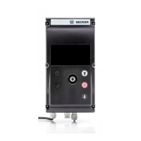
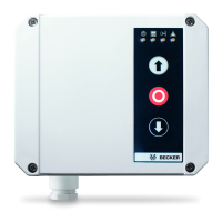
Connection and functions of the switch outputs
Switching outputs
The door control unit has 3 floating relay switching outputs (REL1 and REL2 are changeover contacts, and REL3 is a normally open
contact), see chapter Position of the terminals and complete connecting diagram: P.991: 0 Mechanical limit switching [}53] or
Position of the terminals and complete connecting diagram: P991: 2 Absolute value encoder [}55]). Relays 1 and 2 have a
switching capacity of 230 V AC / 3 A each and relay 3 has a switching capacity of 24 V / 0.5 A. Additional outputs and inputs can be
added with the optional expansion boards M1 and M2.
Table: Overview of output functions:
Function of the switching outputs Value
No function 0
External testing – high active (relay switched on) 1
Wake-up signal for radio safety edge 2
Door position limit position CLOSE 3
Door position limit position OPEN 4
Door position limit position partially open 5
Door position smoke ventilation position 6
Door in motion 7
Outdoor light 8
Warning light 9
Fault indication 10
Locking the door 11
Locking the wicket door 12
Stop light red inside 13
Stop light green inside 14
Stop light red outside 15
Stop light green outside 16
External testing – low active (relay switched off) 17
Warning light flashing, 1 Hz 18
Table: Factory settings for output functions:
Output Parameter Factory setting
REL 1 P.710 3
REL 2 P.720 4
REL 3 P.730 0
REL 4 BDC-M1 P.740 0
REL 5 BDC-M1 P.750 0
REL 1 BDC-M2 P.760 0
REL 2 BDC-M2 P.770 0
REL 3 BDC-M2 P.780 0
REL 4 BDC-M2 P.790 0
External testing
To achieve category 2 according to EN 13849-1, the safety function, e.g. light barrier, pull-in safety device, must be tested. To test
a light barrier or pull-in safety device, the device to be tested is powered via the control unit’s output relay. Testing is performed
before every movement. If the test fails after 0.5 seconds, only operation in dead-man mode is possible. The test may cause a time
delay in the movement.
External testing, low active
During active testing, the power supply to the safety device is switched off and a signal change must occur at the input to the con-
trol unit.
26