Do you have a question about the Becker Beck-O-Tronic 6 and is the answer not in the manual?
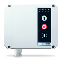
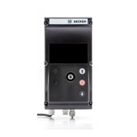
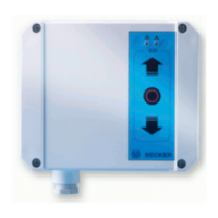
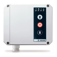
Overview of the BECK-O-TRONIC 6 door control unit and its purpose.
Highlights the key features and advantages of the control unit.
Defines the meaning of warning and informational pictograms used in the manual.
Details warranty conditions and warnings against improper installation.
Work on electrical equipment must be performed by a qualified electrician.
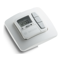
Visual overview of the control unit, buttons, and hand-held transmitter.
Work on electrical equipment must be performed by a qualified electrician.
Electrical work requires qualified electricians or trained personnel; disconnect power first.
Lists and defines abbreviations for various controls and functions of the unit.
Details the operation of each button on the control unit and transmitter.
Explains the meaning of different segment statuses indicating door positions.
Describes the meaning of segment statuses indicating input states.
Procedures for testing safety-related functions like self-tests.
Detailed steps for parameter editing and saving settings.
Details the steps for editing and saving parameter values.
Settings for maximum drive running time.
Configuration for detecting door limit positions.
Selection of the type for Safety Input SE1.
Configuration of SE1 functions for CLOSE and OPEN directions.
Selection of the type for Safety Input SE2.
Configuration of SE2 functions for CLOSE and OPEN directions.
Settings for the automatic reclosing feature.
Sets the stay-open time after exiting the light barrier at SE2.
Configuration for light and warning light functions.
Settings for advance warning times in open and close directions.
Configuration of the reverse travel time.
Setting for automatic reclosing following an emergency stop.
Configuration for OPEN/CLOSE inputs and keypad types.
Settings for pre-limit switch and slat adjustment.
Settings for dead time during reversal and 12V standby output.
Setting the interval for maintenance reminders.
Enabling or disabling parameter adjustments.
Readable information on version number and door movement count.
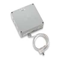
Specifies connections for the main power supply.
Describes the wiring for the light or warning indicator.
Explains the connections for the drive motor and tubular drive.
Details the wiring and function of the emergency stop safety input.
Specifies connections for the 12 V DC output.
Details input types for safety devices and their functions.
Configuration and connection for Safety Input SE1 with various types.
Configuration and connection for Safety Input SE2 with various types.
Details on connecting and configuring the OPEN input.
Details on connecting and configuring the CLOSE input.
Information on connecting and operating the pulse input.
Details on connecting and using the pre-limit switch.
Explains limit switch detection via running time or internal limit switch.
Explains the purpose and setting of dead time during direction changes.
How the control unit operates drives and external/internal limit switches.
Describes the operation of the panic function.
Explains the automatic reclosing feature and its conditions.
Details how the control unit enters and operates in standby mode.
Describes special functions like holiday mode and permanent states.
How to operate the unit in emergency or dead-man mode.
Instructions for enabling or disabling parameter adjustments.
Information on reading the door movement counter.
Explains how the maintenance interval setting works and is displayed.
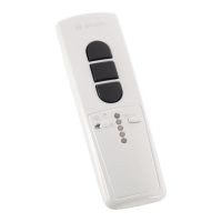
Instructions for using the radio remote control.
Shows images of transmitter types and their functions.
Steps for programming and deleting remote control transmitters.
Instructions for connecting the antenna wire.
Guidance on proper disposal and unit maintenance.
Instructions for cleaning the housing of the control unit.
Detailed list of error codes and corresponding troubleshooting measures.
Troubleshooting for EEprom, motor current, N-relay, OPEN/CLOSE relay, and watchdog errors.
Troubleshooting for ROM and RAM test errors.
Troubleshooting for LS/SE1 and LS/SE2 internal test errors.
Error codes related to SE1, SE2, Emergency Stop, and Pre-limit switch.
Diagram for connecting OSE safety edges.
Key technical data including dimensions, power, and operating conditions.
| Brand | Becker |
|---|---|
| Model | Beck-O-Tronic 6 |
| Category | Control Unit |
| Language | English |