Operating Instructions
19
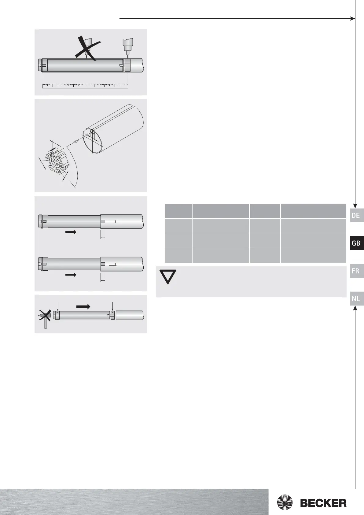
• For profile tubes:
For some drive adapters, tolerances of the channel widths in different roller tubes
can be balanced by turning the drive adapter in a different channel slot. These chan-
nel slots come in different sizes and make it an exact fit possible when the drive is
installed.
• For round tubes:
Release the tube from the motor died in advance, so that the cam of the ring can
also be inserted into the tube. The cam of the ring must not engage with the tube.
For rings without pulling cams, the roller tube must be connected to the ring by a
4.8 x 10 mm sheet-metal screw.
4. Assemble the tubular drive with the relevant ring (A) and drive adapter (B). Insert the
tubular drive with the pre-assembled ring and drive adapter into the tube as shown.
Ensure that the ring and drive adapter are correctly positioned in the tube. (Fig. 7)
The drive adapter of the tubular drive is connected to the roller tube as follows:
Attention
When drilling into the roller tube, never drill near the tubular drive!
The tubular drive must not be hit into the tube or dropped into the
roller tube!
Becker also recommends that the counter bearing be joined to the roller tube.
5. Hang the tube in the bracket and secure the motorhead piece in the drive bracket.
6. Hang the mounted unit consisting of tube, tubular drive and thrust bracket in the
bracket.
5
4
A
B
C
B
3. Before fitting in the barrel, take the measurement from barrel end to the centre of
the drive adapter and mark on the barrel (Fig. 4).
foeziS
]mm[evird
Ø–sebutrettuhsrelloR
]mm[
.xameuqroT
]mN[
swercsgninetsaF
)x4(srevirdrof
54Ø
rocitsalpmm07-06
retpadaevirdtsaceid
05
latem-teehsdedaeh-talf
2897NID01x3.6TSwercs
85Ø
mm021-36
retpadaevirdtsaceid
021
latem-teehsdedaeh-talf
2897NID01x5.9TSwercs
85Ø
mm331-58
retpadaevirdmuinimula
021
61x8Mswercsdedaeh-talf
1997NID
7
AB
6
7,5mm
11mm
R8/17PS(+) - R50/11PS(+)
8,5mm
18mm
R44/14 - R120/11PS(+) PS(+)