Mounting and wiring
BK3xx0 27Version: 4.3.0
3.4.4.2 BKxx50 and BKxx51
The Bus Couplers/Bus Terminal Controllers require an operating voltage of 24V
DC
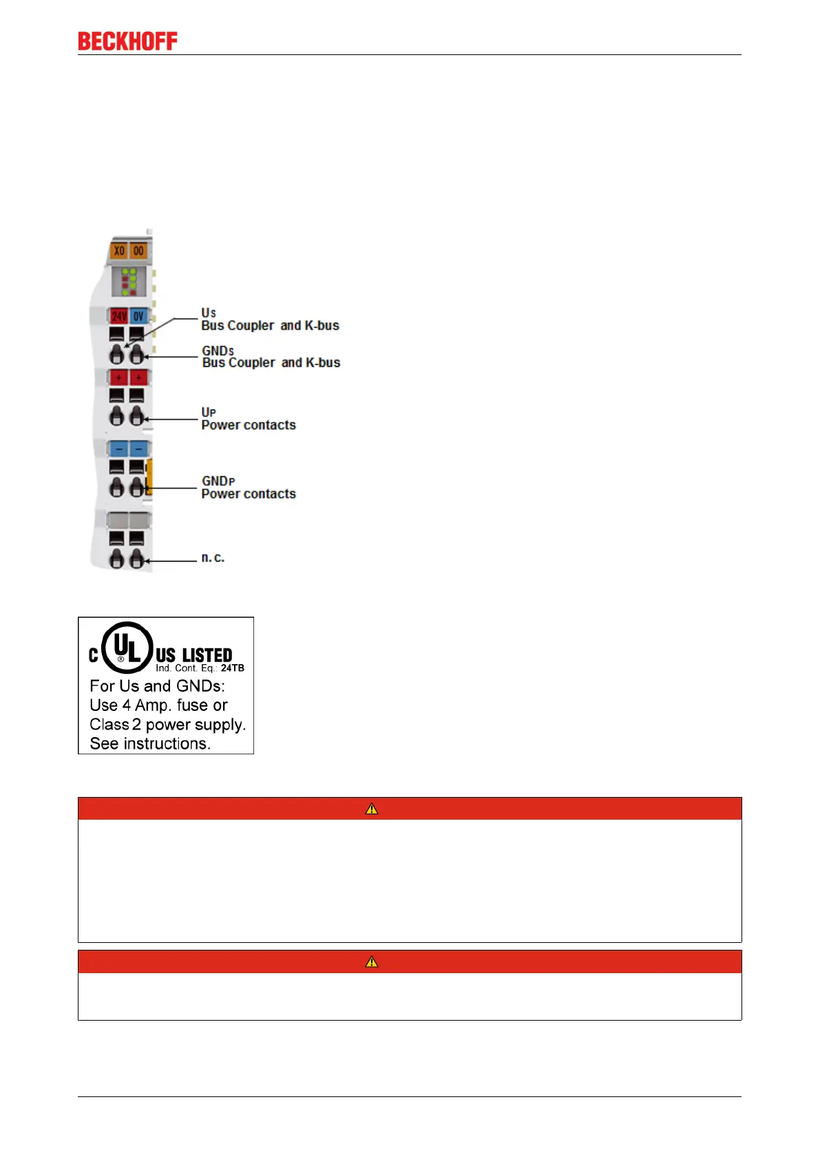
. Use a 4A fuse or a
Class2 power supply to comply with the UL requirements.
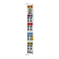
The connection is made by means of the upper spring-loaded terminals labelled Us and GNDs. This supply
voltage is used for the electronic components of the Bus Coupler and Bus Terminal Controllers and (via the
K-bus) the electronic components of the Bus Terminals. It is galvanically separated from the field level
voltage.
Fig.15: Power supply connections for BKxx50 and BKxx51
Fig.16: UL identification
DANGER
Note the UL requirements for the power supply.
To comply with the UL requirements, the 24V
DC
supply voltage for Us must originate
• from an isolated source protected by a fuse of max. 4A (according to UL248) or
• from a voltage supply complying with NEC class 2.
An NEC class 2 voltage source must not be connected in series or parallel with another NEC class 2
voltage source!
DANGER
No unlimited voltage sources!
To comply with the UL requirements, Us must not be connected with unlimited voltage sources.
 Loading...