Do you have a question about the Beckhoff CP68 Series and is the answer not in the manual?
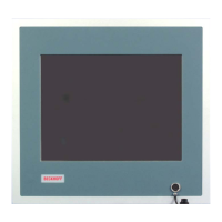
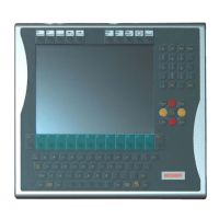
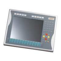
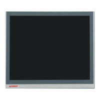
This document describes the Beckhoff Built-in Control Panel CP68xx, a series of industrial control panels designed for various applications in machine and plant engineering. The CP68xx panels feature a TFT display, a touchscreen (optional), and a PC keyboard (optional), all integrated into a front control cabinet.
The Control Panel CP68xx serves as a human-machine interface (HMI) for industrial applications. It is designed to display visual information and allow user interaction through a touchscreen or an optional PC keyboard. The panel's primary function is to provide a robust and reliable interface for controlling and monitoring industrial processes.
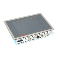
The control panel operates by receiving video signals from an industrial PC via a DVI connection (X 101). Power is supplied to the control panel via the Cage clamp socket (X 102). USB interfaces (X 103, X 104) are available for connecting peripheral devices such as a mouse or keyboard, or for data transfer with an industrial PC. The USB1.1 standard supports a maximum data rate of 1.5 or 12 Mbps.
The control panel does not have its own mains power switch. It is switched on or off as the power supply to the control panel is activated or deactivated. The switching off process involves writing a file to the CF card, which is then deleted. The control software typically validates something to the CF card every few seconds, ensuring data integrity and preventing damage caused by abrupt shutdowns. The control panel's membrane keypad is designed for durability and can be actuated by fingertips or with a touch screen pen. Operators should wear gloves to prevent damage from metal shavings or glass splinters embedded in the glove.
The keyboard codes provide various functionalities:
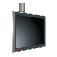
The CP68xx series offers various display sizes and dimensions. For example, the CP6809 has a 6.5" display, while the CP6814 has a 20" display. The dimensions vary accordingly.
Dimensions (W x H x D):
Environmental Conditions:
Shock Resistance (EN 60068-2-6):
Protection Class:
Power Supply:
EMC Compatibility:
Transport and Storage:
UL Certificate of Compliance: The Built-in Control Panel CP68xx from Beckhoff Automation GmbH meets the requirements of Underwriters Laboratories Inc. (UL) standard:
The correspondence of the mentioned product with these requirements is proved by the fact that this product meets with the following single standards:
FCC and Canadian Notice: This equipment has been tested and found to comply with the limits for a Class A digital device, pursuant to Part 15 of the FCC Rules. These limits are designed to provide reasonable protection against harmful interference when the equipment is operated in a commercial environment. This equipment generates, uses, and can radiate radio frequency energy and, if not installed and used in accordance with the instruction manual, may cause harmful interference to radio communications. Operation of this equipment in a residential area is likely to cause harmful interference in which case the user will be required to correct the interference at his own expense. This device does not exceed the Class A limits for radiated emissions as described in the Radio Interference Regulations of the Canadian Department of Communications.
Appropriate Use: The CP68xx Control Panel is designed for industrial application in machine and plant engineering. It is intended to be built into the front of control cabinets. The Control Panel must not be used where there is a risk of explosion.
Connections:
Mounting of the Control Panel: The Control Panel is inserted into a cutout in the control cabinet. Clamping levers are then released with a No. 2.5 Allen key, folded to the side through 90°, and then retightened to secure the panel. It is crucial to ensure that all screw connections between connectors and sockets are tight.
Connecting the Control Panel: The Control Panel must never be connected or disconnected in an area that is subject to explosion hazard. The mains plug of the Control Panel must be disconnected before connecting external devices. During thunderstorms, plug connectors must neither be inserted nor removed. When disconnecting a plug connector, always handle it at the plug, not the cable.
Transport and Unpacking: The specified storage conditions must be observed. The unit is sensitive to strong vibrations and impacts. During transport, the Control Panel should be protected from excessive mechanical stress. The original packaging should be used for transport. If the device is transported in cold weather or is exposed to extreme variations in temperature, ensure that moisture (condensation) does not form on or inside the device. Prior to operation, the unit must be allowed to slowly adjust to room temperature. Should condensation occur, a delay time of approximately 12 hours must be allowed before the unit is switched on.
When unpacking, remove packaging, do not discard the original packaging, check for completeness, keep associated paperwork, check for shipping damage, and notify Beckhoff Service if any damage or inconsistencies are found.
Servicing and Maintenance: The Control Panel is maintenance-free.
Cleaning the Control Panel: The front of the Control Panel can be cleaned with a soft, damp cleaning cloth. Do not use any aggressive cleaning materials, thinners, scouring material, or hard objects that could cause scratches.
Replacing Fluorescent Lamps in the Display: Since fluorescent lamps represent a consumable item in a display, they must be replaced after a few years, depending on the number of operating hours. The fluorescent lamps of the 6.5 inch, 12 inch, and 15 inch displays can be replaced by a technically competent person. Partial disassembly of the display may be required.
Replacement procedure for 6.5 inch display:
Replacement procedure for 12 inch display:
Replacement procedure for 15 inch display:
Lamp sets:
Emergency Procedures: In case of fire, the control panel should be extinguished with powder or nitrogen.
Shutting Down: The device must be fully dismantled in order to dispose of it. The housing can be sent for metal recycling. Electronic parts such as lamps and circuit boards must be disposed of in accordance with national electronics scrap regulations.
Troubleshooting:
Service and Support: Beckhoff and their partners around the world offer comprehensive service and support, making available fast and competent assistance with all questions related to Beckhoff products and system solutions. Contact Beckhoff's branch offices and representatives for local support and service. Beckhoff headquarters can be reached at Eiserstraße 5, D-33415 Verl, Germany. Phone: +49(0)5246/963-0, Fax: +49(0)5246/963-198, E-mail: info@beckhoff.com. Beckhoff Support offers comprehensive technical assistance, including worldwide support, design, programming, and commissioning of complex automation systems, and extensive training programs. Hotline: +49(0)5246/963-157, Fax: +49(0)5246/963-9157, E-mail: support@beckhoff.com. Beckhoff Service supports you in all matters of after-sales service, including on-site service, repair service, spare parts service, and hotline service. Hotline: +49(0)5246/963-460, Fax: +49(0)5246/963-479, E-mail: service@beckhoff.com. If servicing is required, quote the project number of your Industrial PC.
| Brand | Beckhoff |
|---|---|
| Model | CP68 Series |
| Category | Control Panel |
| Language | English |