14 USER MANUAL USER MANUAL 15
5.3. Adjusting the wheels
The wheels are fully tightened (in some models the front wheel is supplied disas-
sembled), if adjust is needed or you need to remove the wheel, tighten the screws
(or quick release) to make sure the front and back wheels are ixed to the front fork
and frame. Check torque table for values.
If a quick release is used, the minimum force to unlock should be at least 70Nm.
The correct position of quick release, when locked should be close to the frame/
fork with the mark “Close” visible.
THRUAXLE with Quick-Release/
Allen Key
1. Position the wheel on the drop-
outs
2. Slide the axle trough the hub
(lever in the open position)
3. Rotate the axle clockwise to
screw on the frame/for or n the
supplied nut (hold tight, no tools
needed), ind the best closing
force. (If it’s an Allen key tighten
to 10Nm and it’s done)
4. Open the lever to the angle of
45º before close
5. Choose the closing position. The
axle doesn’t rotate
6. Close the lever
7. The force required to close
should leave an imprint on your
hand
9mm Quick-Release
1. Position the wheel on the drop-
outs, the axle should be on the
wheel.
2. Rotate the axle clockwise, ind
the best closing force.
3. Close the lever
4. The force required to close
should leave an imprint on your
hand
5. Adjusting your BEEQ ready to ride
Every BEEQ is has its own features and geometry, next you may ind information
to help get it adjusted to each rider.
5.1. Adjusting the Handlebars
The handlebars will be initially adjusted for a general position. To reach a more
comfortable position, it is done by just loosing, adjusting and clamping the nec-
essary screw connection. The maximum torque on the clamping screws is 5Nm
to 7Nm, provided that the component does not indicate any other speciications
Please observe that when adjusting/changing the handlebar, the
response to steering and braking can be adversely aected.
5.2. Adjusting the Saddle
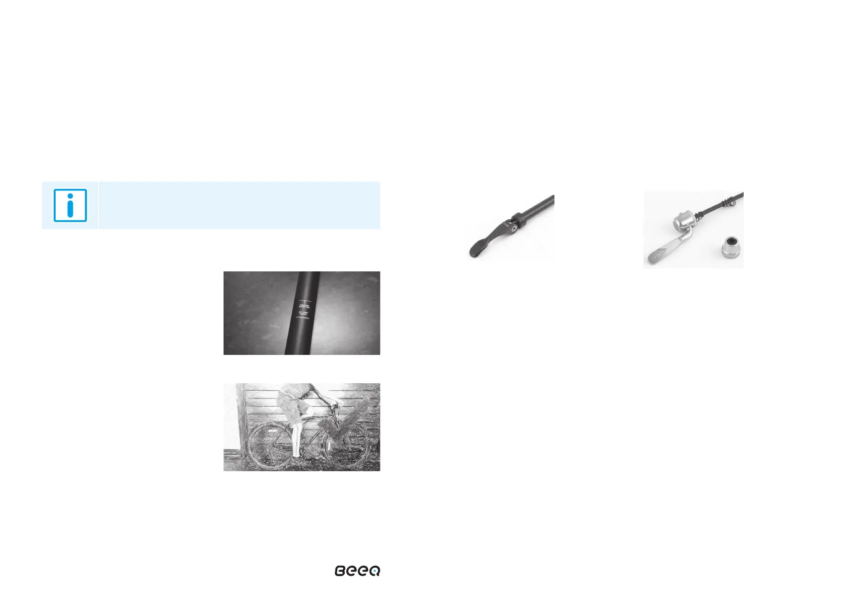
The saddle post must be inserted to at
least the circular safety mark engraved
on the tube.
Minimum insertion
An ideal saddle height is when the knee
is at a soft bend when you are sat on
the saddle with your foot on the pedal
at its lowest point. Adjust the saddle to
this height.
Saddle position
The saddle should be parallel to the ground for maximum comfort. The tight-
ening torque for the saddle mounting screw and saddle post mounting screw
should not be less than 18 Nm.