16 XENYX UFX1604 Quick Start Guide 17
XENYX UFX1604 Controls
(EN)
Step 2: Controls
(1) XLR balanced input.
(2) LINE/HI-Z input.
(3) LINE/HI-Z button. When HI-Z mode is
engaged, you can plug your guitar or bass into
this input without using an external direct
input (D.I.) box.
(4) +48 V Phantom power is used for condenser
microphones that require between 9 V DC and
48 V DC power to operate.
(5) LOW CUT button lters out frequencies below
80 Hz.
(6) GAIN knob adjusts the sensitivity of the MIC
and LINE/HI-Z inputs.
(7) SEND lets you choose to route your input
signal to FireWire/USB pre or post EQ.
(8) COMP(RESSOR) knob adjusts the amount of
compression eect on the channel.
(9) EQ knobs adjust the HIGH, HIGH MID,
LOWMID, and LOW frequencies of
thechannel.
(10) EQ button turns the EQ section on and o.
(11) AUX / FX A and FX B knobs adjust how much
of the channel’s signal is sent to the AUX SEND
jacks and/or the internal FX processors.
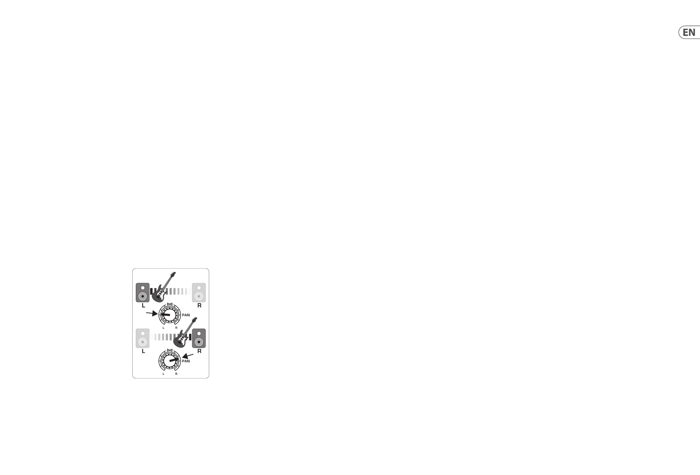
(12) PAN knob positions the channel’s signal in the
stereo eld.
(13) MUTE button removes the channel from the
MAIN MIX and sends it to the ALT 3-4 bus.
(14) SOLO button sends the channel signal to
the solo bus (Solo in Place) or to the PFL bus
(Pre-Fader Listen).
(15) LEVEL METER shows the input signal level of
the channel’s input signal.
(16) CHANNEL FADER adjusts the channel volume.
(17) LINE IN left and right input jacks for mono or
stereo signals.
(18) LINE/FW 1-2 (3-4) button allows the
signal from a computer to be routed via
FireWire/USB to these channels and controlled
by the EQ and AUX and Fader functions.
NOTE: All FireWire (FW) routing switches work
for USB connectivity to a computer and for the
USB stand-alone mode depending on how you
have the MODE selector switch (50) set.
(19) 4–band EQ for the stereo channels.
(20) BAL(ANCE) knob controls the relative volume
of the left and right input signals before they
are routed to the stereo main mix bus.
(21) CONTROL ROOM OUT jacks carry the summed
eects and main mix signals, as well as soloed
channel signals.
(22) MAIN OUT jacks for connecting line level signal
to powered speakers or external amplier.
(23) ALT 3-4 OUT jacks for connecting line level
signal of an alternate stereo mix to a recording
device, powered speakers or external
amplier. Can also be used for subgrouping.
(24) CD/TAPE IN and OUT for connecting a stereo
source or for sending the main signal to an
external recorder.
(25) PHONES jacks for connecting headphones.
(26) INPUT level meters display the signal input
intensity going into the FX A or FX B bus.
(27) FX A eect knob selects which eect is
applied to the signal (same for FX B).
(28) EDIT knob adjusts the eect’s main parameter.
(29) FX ON button turns the eect on and o.
(30) The TAP/SELECT button performs two
functions. Hit the button several times in the
tempo of the music piece to adapt the delay
time of presets 9 and 15 or the modulation
speed of presets 10-12. The button will
start ashing in the corresponding tempo.
TheTAP/SELECT button also changes the
characteristic of the second parameter on
presets 1-8, 13-14 and 16. By pressing the
button you can toggle between two dierent
values (light o/on) for the second parameter.
(31) FW/USB LED indicates the computer is
connected (based on the selection switch on
back panel).
(32) VU METER displays the MAIN OUTPUT
signallevel.
(33) MODE button determines whether the SOLO
button operates in ‘Solo in Place’ (buttonout)
or ‘Pre-Fader Listen’ (button in). PFL is
preferred for gain setting purposes.
(34) PHONES knob controls the volume level of the
PHONES jacks.
(35) CONTROL RM knob controls the volume of the
CONTROL ROOM OUT jacks.
(36) SOURCE monitoring select buttons route the
signal to either the CONTROL RM/PHONES
jacks (left column) or the MAIN MIX
(rightcolumn).
(37) PRE/POST fader select buttons for all
4AUXSEND busses.
(38) AUX SEND 1-2 to FW 13-14 switch disables
mixer channels 13-14 from being sent via
FireWire/USB so that AUX SEND 1-2 can be
routed to a computer (for recording, etc.).
(39) Destination routing switches for AUX RETURN
3 source signal.
(40) Destination routing switch for AUXRETURN 4
(to MAIN bus or CONTROLROOM/PHONESbus).
(41) MUTE, SOLO and output LEVEL knobs for
ALT3-4 bus.
(42) Assign to FW 15-16 switch sends the MAINMIX
signal via FireWire/USB to computer or
external USB drive when in the ON position.
When o, mixer channels 15-16 can be sent
via FireWire/USB.
(43) PRE/POST switch sends the MAIN MIX
signalto FireWire/USB pre or post main fader
(requiresASSIGN TO FW 15-16 switch to
beon).
(44) TALKBACK MIC (built-in), LEVEL knob (adjusts
TALKBACK microphone volume), DESTINATION
switches and TALK button (press while
talking).
(45) 16 TRACK USB DRIVE RECORDER/MIDI
TRANSPORT CONTROL for use while connected
to a computer via FireWire or USB as a MIDI
Machine Control. Also used In STAND ALONE
MODE for controlling the internal USB recorder
functions.
(46) MAIN MIX stereo fader adjusts the overall
output of the mixer.
(47) POWER ON turns the mixer on.
(48) USB DRIVE jack for use with external USB hard
disk drives (recommended) or thumb drives in
STAND ALONE mode.
(49) USB jack for connecting to a computer.
(50) MODE selector switch.
(51) FireWire jack for connecting to a computer.
(52) MAIN OUTPUTS for sending MAIN MIX via
balanced XLR cables.
(53) AUX(ILIARY) SENDS route the 4 auxiliary bus
signals via balanced or unbalanced ¼"cables.
(54) CHANNEL INSERTS allow you to connect
external eects to the individual channels
(1-8) PRE-FADER and PRE-EQ.
(55) AUX(ILIARY) RETURNS allow you to bring a
stereo eects signal routed from an AUXSEND
jack, through a processor, backinto the
designated auxiliary bus. Theseinputs can
also be used to connect additional line sources
such as keyboards.
 Loading...