Additional Installation Tips
6 Additional Installation Tips
When experiencing communication problems in for example noisy environments
or when operating close to temperature limits, the following recommendations
are to be noticed.
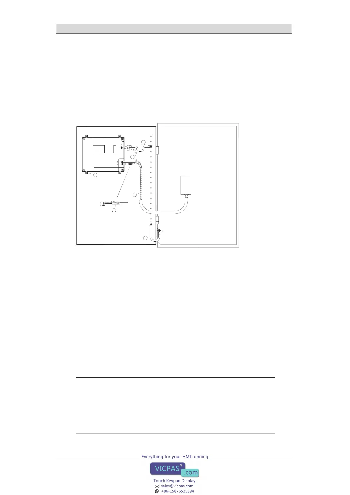
6.1 Grounding the Operator Panel
1
2
3
4
5
6
Door
Operator panel
Ferrite core
Mounting plate in the cabinet
Power supply
24 V DC
5350
The operator panel’s mounting clamps do not provide a secure grounding
connection between the panel and the device cabinet, see 1 in drawing above.
1.
Connect a wire that is sized correctl
y according to local electrical codes
between the operator panel’s quick
-connect plinth and the panel’s chassis, see
2indrawingabove.
2.
Connect a 6 or 4 mm
2
wire or grounding braid between the panel’s chassis and
the closest grounding point on the door, see 3 in drawing above.
3.
Connect a strong but short grounding braid between the door and the device
cabinet,see 4 in drawing above.
4.
Twist the cables onto the 24 V DC feed, see 5 in drawing above.
2 turns around the ferrite core provide 4 times the suppression of 1 turn.
3 turns around the ferrite core provide 9 times the suppression of 1 turn.
A ferrite core suppresses disturbances to the 24 V feed, see 6 in drawing above.
Note:
The grounding wires should be short and t he conductor should have a large area.
A long, thingrounding wire hasa very high impedance (resistance) at high frequencies
and will notguide disturbances to theground.
Multi-wireconductors arebetter than singlewireconductorswiththesamearea.
A braided conductor wire with the same area iseven better. The bestis a short,thick
grounding braid.
Beijer Electronics, MAEN774E
18