6. HMI Panel Drawings
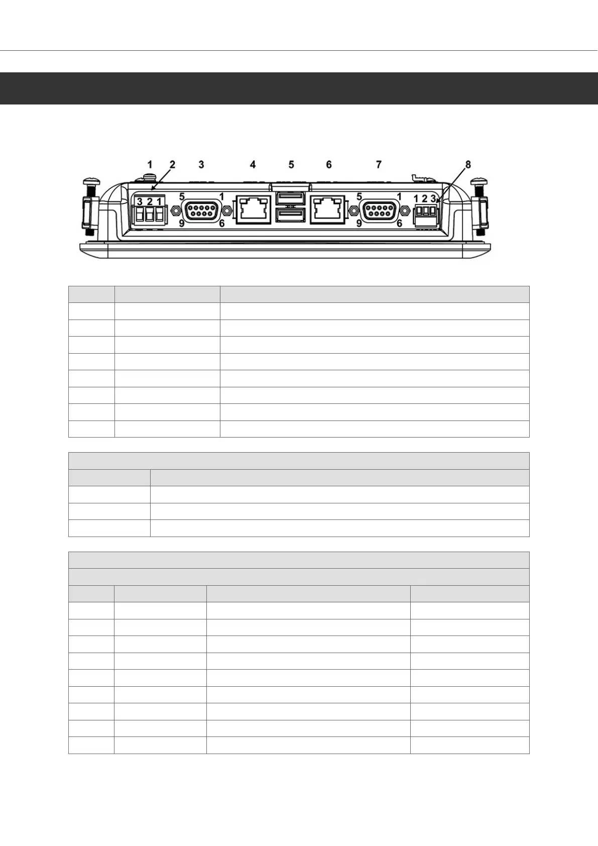
6.1. Connectors
Pos Connector Description
1 Ground screw Screw to connect functional ground
2 Power supply 3-pin screw connector, +24V DC (18-32V DC)
3 COM-A DSUB (9-pin, female), serial communication port
4 LAN-A RJ 45 (shielded), 10/100Mbit
5 USB-A/B USB 2.0 Host, max output current 500mA
6 LAN-B RJ 45 (shielded), 10/100Mbit
7 COM-B DSUB (9-pin, female), serial communication port
8 COM-C 3-pin screw connector
Power supply pin assignment
Pos Description
1 Vin+ (Main input supply voltage)
2 Vin- (Power ground)
3 FG (Frame Ground)
COM-A
Serial port pin assignment
Pin COM 1 COM 2 COM 3
1 RS-422 TX+ or RS-485 Tx+/Rx+
2 RS-232 RxD
3 RS-232 TxD
4 RS-422 RX+ RS-485 Tx+/Rx+
5 GND GND GND
6 RS-422 TX- or RS-485 Tx-/Rx-
7 RS-232 RTS
8 RS-232 CTS
9 RS-422 RX- RS-485 Tx+/Rx-
HMI Panel Drawings
2023-09 18 Beijer Electronics, MAEN330

 Loading...