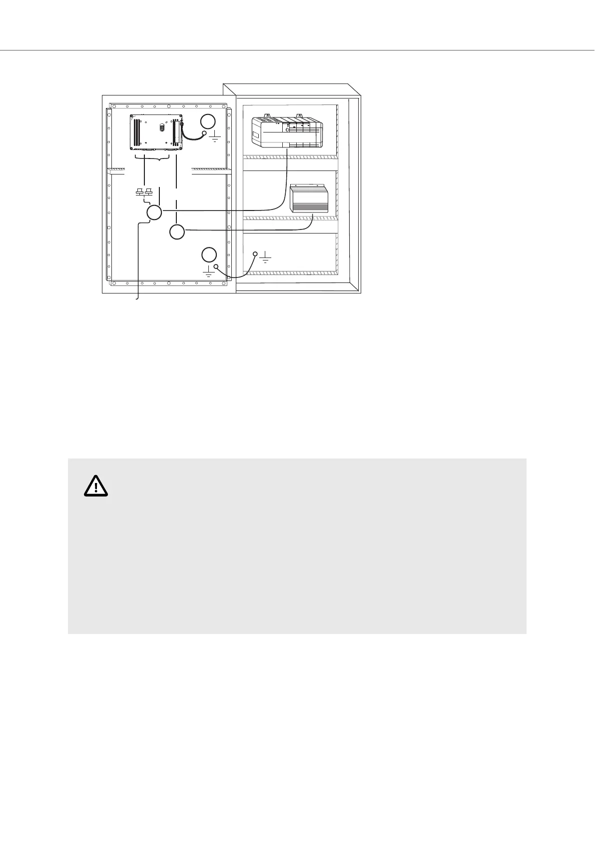
24V DC
RS232/
RS422/
RS485
24V DC
A
D
Controller
Power
B
Ethernet
C
The image is illustrative only and may differ slightly from the actual panel.
• Connect cable A.
• Connect cable B, using 14-20 AWG (2.08–0.52 mm
2
), 180–220 N-cm torque.
• Connect cable C.
• Connect cable D. The recommended cross-section of the cable is 1.5 mm
2
.
8. Carefully remove the protective film over the HMI panel display, taking care to avoid static
electricity that could damage the panel.
CAUTION
• The HMI panel must be brought to ambient temperature before it is started up. If
condensation forms, ensure that the HMI panel is dry before connecting it to the
power outlet.
• Ensure that the HMI panel and the controller system have the same electrical
grounding (reference voltage level), otherwise errors in communication may occur.
• Ensure that the voltage and polarity of the power source is correct.
• Separate high voltage cables from signal and supply cables.
• Shielded communication cables are recommended.
3.2.1. Connections to the Controller
For information about the cables to be used when connecting the HMI panel to the controller, please
refer to the help file for the driver in question.
3.2.2. Other Connections and Peripherals
Cables, peripheral equipment and accessories must be suitable for the application and its
environment. For further details or recommendations, please refer to the supplier.
Installation
2023-09 12 Beijer Electronics, MAEN330
 Loading...