1
6/16 - Subject to change. © Belimo Aircontrols
USA
, Inc
2-
eed Fan
etu
n
m
z
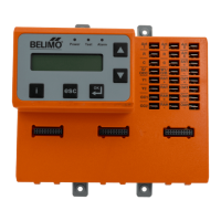
Setup and Configuration
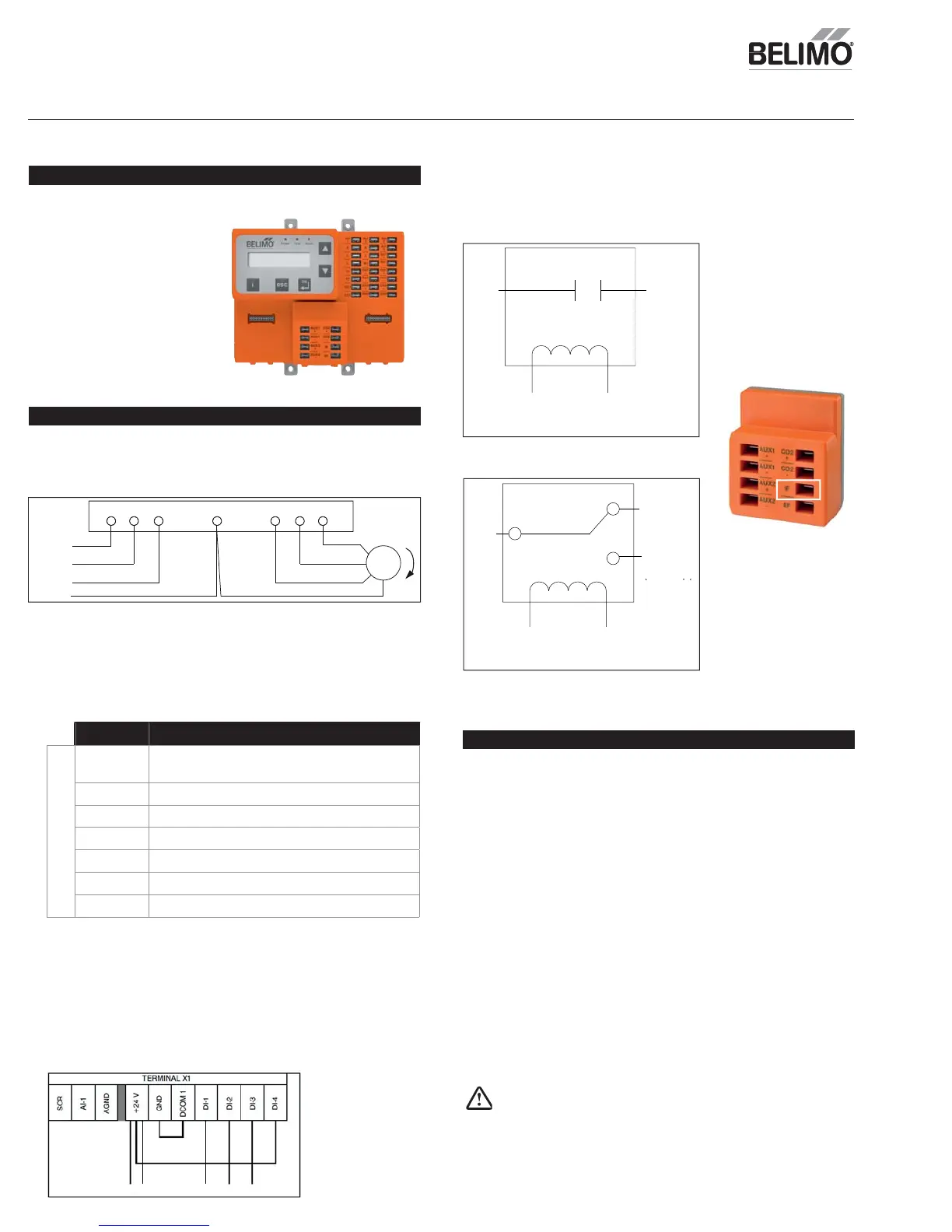
2. Connecting them into the following, utilizing the IF connection at the
CON-ZIP-EM.
Setting up the ZIP Economizer with Variable Frequenc
Drive
1. You will need a VFD rated for
supply fan HP.
2. You will need to have a ZIP
Economizer ECON-ZIP-BASE and
an Energ
Module ECON-ZIP-EM
3. You will also need a separate
PDT relay for integration, and
PST for fan enabling.
Before Getting Started
Wiring VFD to ZIP Economizer
Wire the VFD according to the manufacturer’s instructions. Ensuring line
volta
e to the drive, and wirin
the output of the VFD to motor per dia
ram
elow.
Verify that the motor rotation is correct. If not, switch 2 of 3 wires from VFD
t
m
t
r
1. Locate the VFD Digital Inputs, as well as an
pertinent High, Low Speed
es
gnat
on
Reference Drive Control Terminal Description
i
ital Inputs- X1 Terminal
+
Auxiliar
voltage output 24 VDC / 250 mA
(reference to
ND), short circuit protected
ND
ux
ar
vo
tage output common
D
M Digital input common. Jumper to
ND.
tart/stop. Jumper to +24V
Pro
ram to 40 Hz. Wire to
PDT N
contact.
Program to 60 Hz. Wire to
PDT N
contact.
afety interlock. Jumper to +24V.
Example VFD Terminal Desi
nations
an enable rela
; single pole, single throw
3. Power RTU and enter
ettings menu.
Drive
U1 V1 W1
GND U2 V2 W2
Motor
GND
L3
L2
L1
Input
Programming Indoor Fan Settings
en a
s a
e
, up to t
ree
a
t
ona
sett
ngs w
e requ
re
a. Low
p Vent Min – When a 2
peed strategy is used to save energy,
an additional Vent Min Pos needs to be entered for low speed operation
due to less available static pressure from the fan. This position will be
reater than Vent Min Pos, however equal the same measured airfl ow
t
v
l
b. Low
p D
V Min - When a 2
peed strategy is used to save energy,
an additional D
V Min Pos needs to be entered for low speed operation
due to less available static
ressure from the fan. This
osition will be
greater than D
V Min Pos, however equal the same measured airfl ow
ate va
ue
c.
ow
x
an
os -
en a
spee
stategy
s use
to save energy, an
additional Exh Fan
n Pos needs to be entered for low s
eed o
eration
due to less available static pressure from the fan. This position will be
reater than Exh Fan
n Pos, however equal the same measured airfl ow
ate value.
These values should be set to provide the same airfl ow of outside air
OA
and
xhaust as when fan is operating at full speed. Due to less pressure generated
the fan, this value is t
picall
a higher percentage open value.
24V
I
Start/
top)
ARNIN
Live Electrical
omponents
urin
installation, testin
, servicin
and troubleshootin
of this
product, it may be necessary to work with live electrical components. Have a
uali
ed licensed electrician or other individual who has been properly trained
in handlin
live electrical components per
orm these tasks. Failure to
ollow all
electrical sa
et
precautions when exposed to live electrical components could
result in death or serious in
ur
.
he control circuit inputs to the VFD are 24 VDC signals. This voltage is sourced
from the VFD at its terminal stri
X1, +24V. The s
eed in
uts are received at X1
terminals (DI--2) for low speed (40HZ) motor operation and (DI--3) for high
spee
motor operat
on.
en ne
t
er
nput
s present, t
e
w
s
ut
the fan motor off.
Utilizing the nomenclature from the example VFD Terminal Designations table,
pull the following items from the terminal block for Digital Inputs.
ingle pole, double throw rela
24V
VFD
IF C
DI3 (High Sp)
DI2 (Low Sp)
24V
DI3
High Sp
Low S
T
Termina
ECON-ZIP-EM