6/16 - Subject to change. © Belimo Aircontrols
USA
, Inc
ZIP E
n
miz
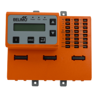
Setup and Confi
uration
uick
etu
MMI Keypad
Moves up through the
menu on the same level.
Will increase values by
one increment at a time.
When setting values
holding key down will
fast scroll
Moves down through the
menu on the same level.
Will decrease values by
one increment at a time.
When setting values
holding key down will fast
scroll.
Enter sub menu level.
Start editing a setting.
Store an entered
value.
esc
Escape sub menu to
next higher level.
Cancel current actions.
i
Show additional
information on the
current menu Item
when “i” appears in
lower right of display.
Functions
. “Monitor Live Conditions” is used to display settin
s and live values.
. “Settin
s” is used to parameterize the ZIP Economizer.
Note: Devices 1 is
for CC1, CC2, EF, IF; Devices 2 is for OAH, RAH
. “Present Devices” is used to verif
that the ZIP Economizer's Auto Detected
connections are terminated
ro
erl
. I
connected device is not shown,
verify wiring. If wiring has continuity and device is verifi ed operational
e-enter “Settin
s” and enable missin
device by chan
in
from “Auto” to
Av
il
l
”
r “In
t
ll
”
4. “Al
rm
” i
t
vi
w
rr
nt
n
hi
t
ri
l
l
rm
n
l
t
nadvertentl
caused alarms.
5. “Service and Commissionin
” submenu is used to operate the RTU in
Manual Mode” or to perform “Acceptance Test”. “Settin
s” must to be
com
leted to access.
. “Status” is a display of the current operatin
mode. It can be accessed
by pressin
”esc”. The action o
pressin
any key will drop the user down
from Status to the next level, so repeatedly pressin
“esc” will to
le the
dis
la
between
tatus and Monitor Live
onditions. (Note: If status
Setup incomplete” is displayed the RTU coolin
operation will be
isabled and additional
arameters must be set to achieve “Setu
omp
ete
.
Installation
1.
hut off power to RTU before beginning installation.
2. Note orientation, opening rotation, and spring return rotation of damper
assembly. Mount Actuator to
utside Air and Return Damper assembly.
To ensure tight outside air shuto
; while tightening actuator clamp push
am
er c
ose
.
3. Terminate required Inputs and
utputs(I
): For the ZIP Economizer
o
function correctly, the following I/O, at a minimum, are required to be
terminated, wired, and functioning (R, C, Y1, Y2, G, CC1, OAT, SAT, ACT1,
CT2, ACT3, ACT5
. See wirin
dia
rams
4.
ensor confi guation: The ZIP Economizer automatically detects sensors
ttached and automatically con
gures
or single dry bulb, single enthalpy,
i
erential dr
bulb and di
erential enthal
Settings
“
ettings” is the menu displayed when the ZIP Economizer is fi rst powered.
Press “
K” to parameterize required settings. Reference above Keypad Key
defi nition instructions and navi
ate as needed.
ARNIN
ive Electrical Com
onents
During installation, testing, servicing and troubleshooting of this product, it may be
necessary to work with live electrical components. Have a qualifi ed licensed electrician or other
individual who has been properly trained in handling live electrical components perform these
tasks. Failure to follow all electrical safety precautions when exposed to live electrical
omponents could result in death or serious injury