6/16 -
ubject to change.
Belimo Aircontrols (U
A), Inc
Wiring
n
m
z
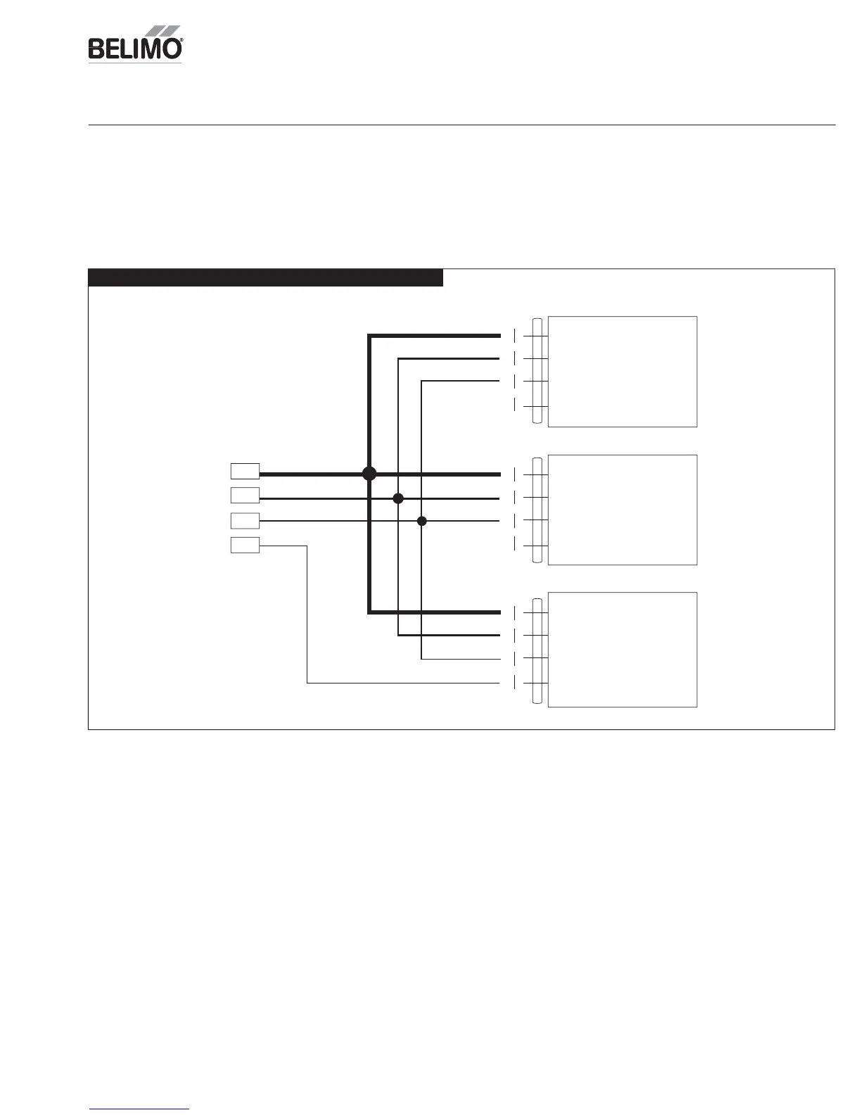
Multiple Actuator
onfiguration
When usin
the ZIP Economizer on a Rooftop Unit
RTU
that has more than one damper that is not mechanically linked, the ZIP Economizer can drive a maximum of
(3) -SR actuators. The actuators must be wired in parallel with the ACT3 output from the ZIP Economizer. The ACT5 feedback input on the ZIP Economizer should be
wired to the
utside Air Damper actuator feedback wire.
Wirin
for the multiple actuator confi
uration is shown in the illustration below; please ensure to follow all warnin
s and cautions listed in the actuator mountin
instructions. Any combination of TFB24-SR, LF24-SR, NFB24-SR, and AFB24-SR can be mounted in this arran
ement.
1 Common
2 Hot
3 Y1 Input
5 U Output (Feedback)
1 Common
2 Hot
3 Y1 Input
5 U Output (Feedback)
1 Common
2 Hot
3 Y1 Input
5 U Output (Feedback)
ACT 1
ACT 2
ACT 3
ACT 5
Exhaust Air Damper
Return Air Damper
Outside Air Damper
ZIP Economizer I/O
onfi
urin
Multiple Actuator