6/16 - Subject to change. © Belimo Aircontrols
USA
, Inc
. Setting PPM range (only required if sensor is confi gurable for other
anges).
. Power RTU and enter Settings Menu.
Note: When the CO
sensor is powered and 0-10 VDC is available at CO
2
+
and CO
2
, the ZIP Economizer will recognize the C
2
presence and the
rompt to set up CO
settings
5.
etting D
V settings.
a. With single speed indoor fan, onl
2 DCV settings are required
i. DCV Min Pos – This is the minimum occupied or zero occupanc
entilation rate expressed in damper percent open
Title 24 2013
ection 120.1(b)2; A
HRAE 62.1
ection 6.2.7).
ii.
2
PPM
et Pnt – This is the
2
n
ntr
ti
n th
t i
ir
in th
pace
t
e
sect
on
.
c
. prescr
e
as
ppm p
us
outdoor air
concentration assumed to be 400ppm = a set point of
ppm
.
ECON-ZIP-EM and CO
sensor can be added during or after initial set up
1. A CO
sensor is needed with the
ollowin
characteristics
a. Output that is 0-10 VDC
b. Range of 0-2000ppm
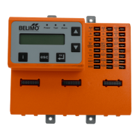
2. Attach the Energ
Module ECON-ZIP-EM to the ZIP Economizer
E
N-ZIP-BA
E.
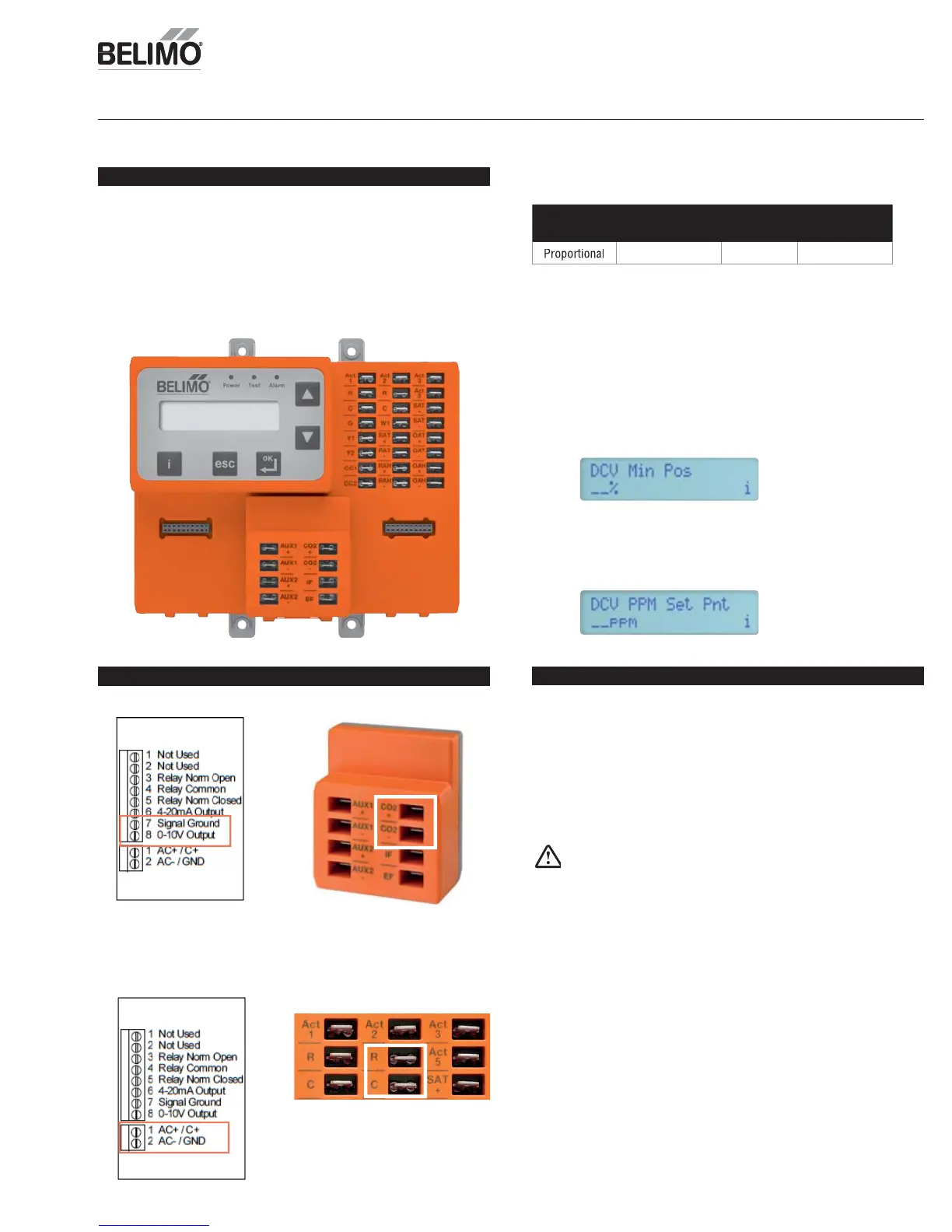
Before Getting Started
Wiring CO
2
Sensor to ZIP Economizer
1. Wire
sensor 0-10 VDC output to ECON-ZIP-EM CO
sensor
nput
Operation
Type of
Output
Ventilation Rate
(cfm/Person)
Analog
Output
CO
2
Control
Range (ppm)
ny 0-10V 0-2000
The ZIP Economizer lo
ic will control the outside air damper position based on
ace CO
dilution needs. If the
2
value is low, the dam
er shall remain at DCV
Min Pos when not in free cooling. When the
concentrat
on r
e
a
ove t
e
PPM
et Pnt (as the space becomes more populated), then the damper will
tart to modulate towards Vent Min Pos to maintain level at
PPM
t Pnt.
When the
concentrat
on
rops
n t
e space
t
e space popu
at
on
ecreases
he damper will start to modulate back towards D
V Min Pos
2. Wire
sensor power.
Note: If RTU transformer VA is suffi cient R/
terminals ma
be used on
ZIP E
n
miz
r.
Exam
le
ensor Diagram
Exam
le CO
Sensor Diagram
ARNIN
Live Electrical Com
onents
During installation, testing, servicing and troubleshooting of this
product, it ma
be necessar
to work with live electrical components. Have a
qualifi ed licensed electrician or other individual who has been properl
trained
in handling live electrical components perform these tasks. Failure to follow all
lectrical safet
precautions when exposed to live electrical components could
resu
t
n
eat
or ser
ous
n
ur
Demand
ontrol Ventilation
etu
ZIP E
n
miz
Setup and Confi
uration