6/16 - Subject to change. © Belimo Aircontrols
USA
, Inc
Freeze Protect
on
• Outdoor air is suitable “for free cooling”
• Y1 may or may not be energized depending on thermostat call for stage
1 cooling.
• Y2 may or may not be energized depending on thermostat call
or stage
2 coolin
.
• W1 may or may not be ener
ized dependin
on thermostat call
or sta
e
1 heating.
• G input is energized indicating occupied state of operation
• Compressor 1 is de-energized
.
• Compressor 2 is de-ener
ized
.
• Fan Speed may or may not be energized (indoor fan is operating on high
r low speed). See Indoor 2 Speed Fan sequence under Energy Module
O
tion Functions
.
• Exhaust Fan is of
• Damper Pos output is modulated
rom minimum to closed to maintain
dischar
e air setpoint.
Possible Modes of O
eratio
: Heating , Free Cooling and Ventilation.
Energy Module Option Functions
1
Pur
e
(Purge Control in Settings Menu must be turned on to enable and 24 VAC
app
e
to
1
• Outdoor air may or may not be suitable “for free cooling”
• Y1 may or may not be ener
ized dependin
on thermostat call for sta
e
1 coo
ng.
• Y2 may or may not be energized depending on thermostat call for stage
2 coolin
.
• W1 may or may not be energized depending on thermostat call for stage
1
eat
ng.
• G input may or may not be energized (occupied or unoccupied state)
• Compressor 1 may or may not be ener
ized dependin
on thermostat call
for stage 1 cooling
• Compressor 2 may or may not be ener
ized dependin
on thermostat call
or stage 2 cooling
• Fan Speed may or may not be energized (indoor fan is operating on high
r low speed
.
ee Indoor 2
peed Fan sequence under Ener
y Module
O
tion Functions
.
• Exhaust Fan is o
• Damper Pos output goes to value set in Purge Dmp
et.
Possible Co-existin
Modes of Operation
:
echanical Cooling, Heating.
amper
verride
IF Remote Dmp Cntrl is turned on (enabled) in Settings men
AND
powered
THEN Damper Pos will go to the value of the signal input (0-10 VDC) at
2
ote: If outdoor air is suitable for “free coolin
” and damper is override to
closed position, there will be no coolin
.
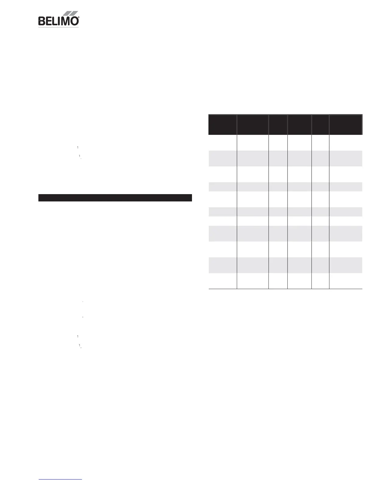
ndoor 2 S
eed Fan
Thermostat
Signal
Economizing
Available
OAT Energy
Module
Fan Relay
Fan
Speed
ZIP Econ /
RTU Mode
G, Y1,
n
t Y2
o
/
Closed
o
Stage DX
, Y1,
n
t Y2
es
50º
pen
ig
conomizing
G
Y1
n
t
2
º
l
conom
z
ng
G, Y1, Y
O
en
g
Stage DX
G, Y1, Y
Open
g
ntegrate
n
m
z
r
G, W1
Open
g
eat
ng
W1
es
en
eat
n
G
not Y1
n
t
1
l
nt
t
, not Y1,
not
1
es
losed
o
ent
at
o
not
not
1
not
O
en
ff Unoccu
ied
not G
not
1, not
Open
ff
noccup
e
When indoor fan is on hi
h speed, the hi
h speed fan minimum damper
position setpoints Vent Min Pos and D
V Min Pos will be referenced as the
inimums
or damper control.
When indoor fan is on low speed, the low speed fan minimum damper position
set
oints Low S
Vent Min and Low S
DCV Min will be referenced as the
inimums for dam
er control.
t
: Indoor fan speed will operate accordin
to the above table whether in
ccu
ied or Unoccu
ied.
te: If RTU equipped with fan speed switchin
relays from the factory, an
Ener
y Module is not required to set up 2 Speed Fan. See 2 Speed Fan Op in
settin
s menu
or more in
ormation
ZIP E
n
miz
Method of O
eration