6/16 - Subject to change. © Belimo Aircontrols
USA
, Inc
E
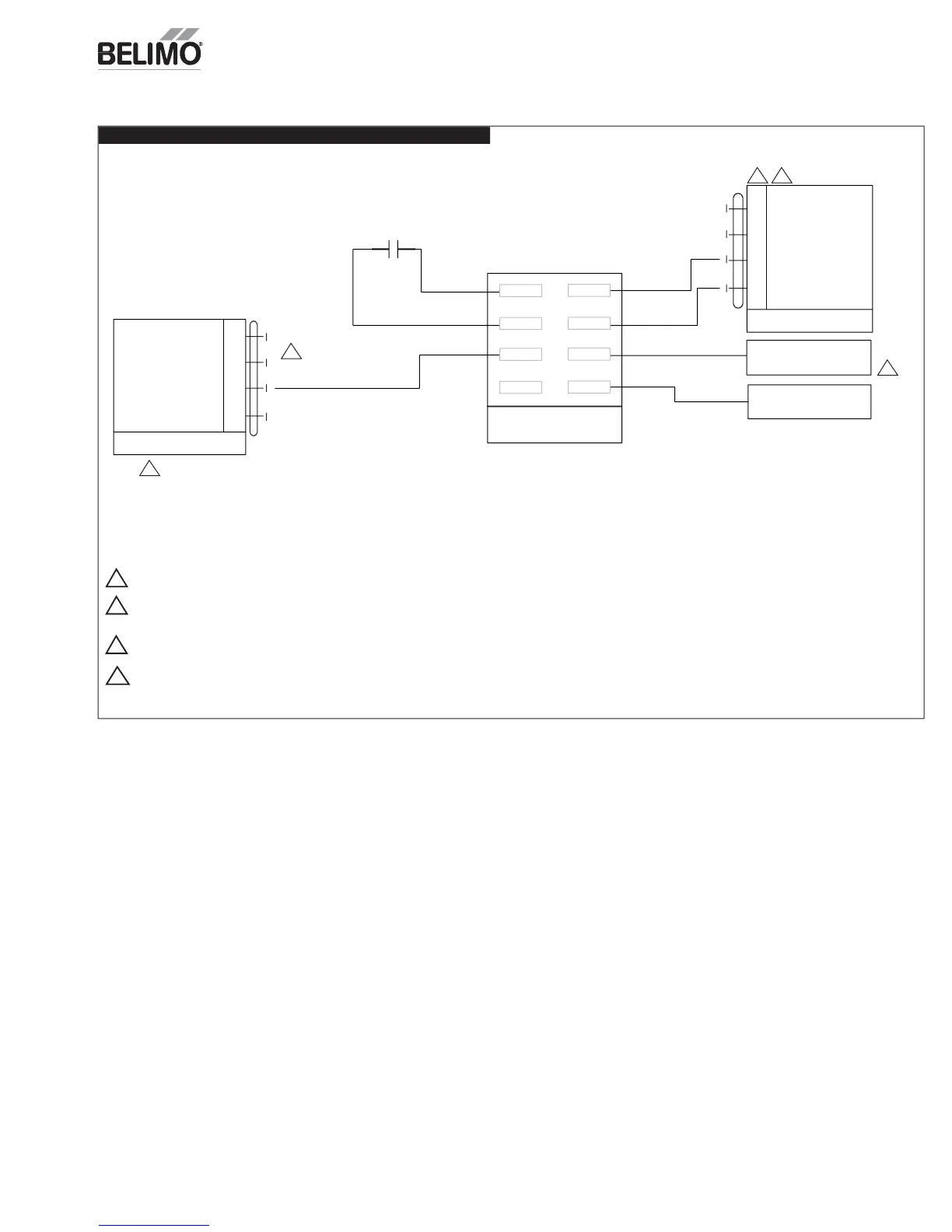
N-ZIP-E
ZIP Econom
zer™ Ener
y Modul
Wiring Diagram
CO2 -
CO2 +
Purge Contact
Thermostat
24 VAC
AUX1+
AUX1 -
AUX2 +
Indoor Fan Low
Speed Relay / VFD Enable
Exhaust Fan
Circuit
CO2 Sensor
1 - Common
2 +
3 + Y Input, 0 to 10 VDC
4 - 0 to 10 VDC
SGA24 SGF24
Common - 1
+ 2
Y Input, 2 to 10 VDC + 3
2 to 10 VDC + 4
AUX1 +
CO2 +
AUX1 - CO2 -
AUX2 +
AUX2 -
IF
EF
ECON-ZIP-EM
52
55
54
50
50
Power source should be the same as ECON-ZIP-BASE.
50
Not supplied by Belimo.
Sold separately by Belimo
54
55
W1 must be wired for Heat Pump operation if conventional thermostat is used in conjunction with Defrost Board.
If Thermostat and RTU use O/B control reversing valve position, O/B must be wired to W1 on ECON-ZIP-BASE.
52