213
J20741 - Subject to change. © Belimo Aircontrols (USA), Inc.
LM
Wiring Diagram
LMX24-SR… - Typical Specification:
Proportional control damper actuators shall be electronic
direct-coupled type, which require no crankarm and linkage
and be capable of direct mounting to a shaft from 1/4” to 5/8”.
Shafts up to 3/4” diameter can be accommodate with an
accessory clamp. Actuators must provide proportional
damper control in response to a 2 to 10 VDC or, with the
addition of a 500Ω resistor, a 4 to 20 mA control input from
an electronic controller or positioner. Actuators shall have
Brushless DC motor technology and be protected from over-
load at all angles of rotation. Actuators shall have reversing
switch and manual override on the cover. If required, actua-
tor will be provided with screw terminal strip for electrical
connections (LMX24-SR-T). Run time shall be constant and
independent of torque. A 2 to 10 VDC feedback signal shall
be provided for position indication. Actuators shall be cULus
listed, have a 5-year warranty, and be manufactured under
ISO 9001 International Quality Control Standards. Actuators
shall be as manufactured by Belimo.
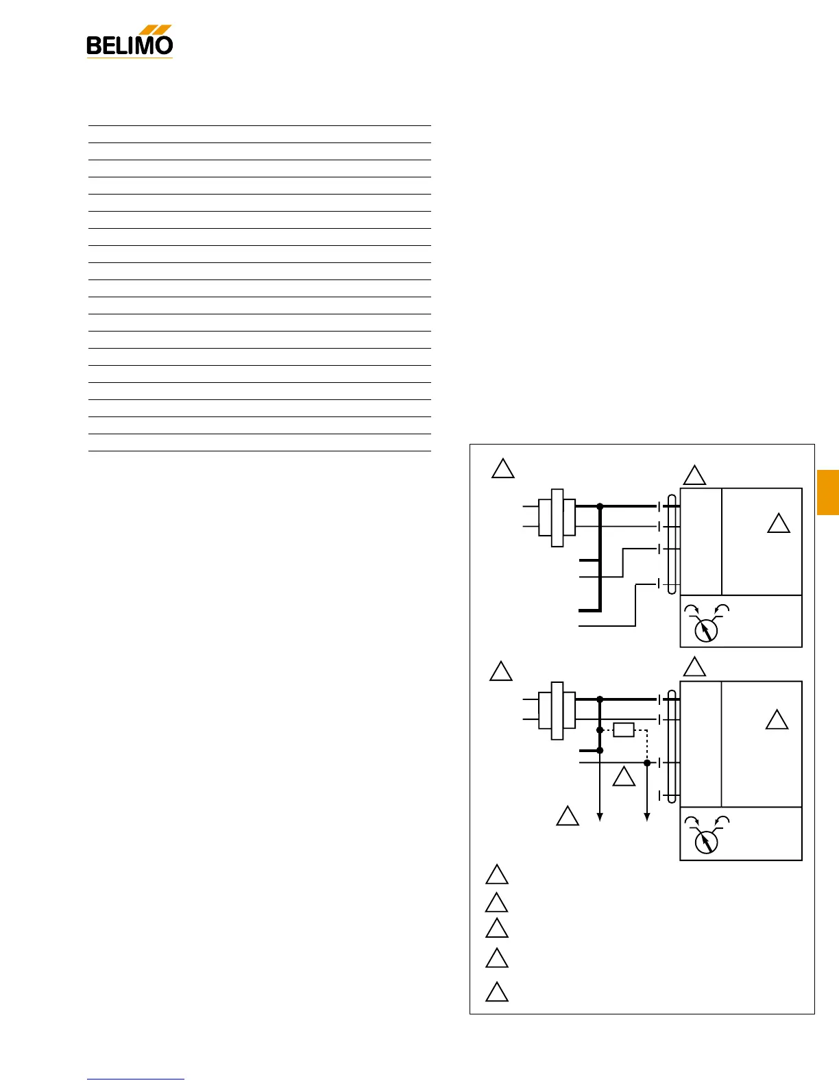
LMX24-SR (-T)
Proportional Control, Non-Spring Return, Direct Coupled, 24V, for 2 to 10 VDC and 4 to 20 mA
1
2
3
24 VAC Transformer
Blk (1) Common
Red (2) Hot +
Wht (3) Y Input, 2 to 10V
Org (5) U Output, 2 to 10V
LMX24-SR
Line
Volts
2 to 10 VDC
Control Signal
(–)
(+)
–
1
2
3
Provide overload protection and disconnect as required.
Actuators may be connected in parallel. Power
consumption and input impedance must be observed.
Actuator may also be powered by 24 VDC.
4
The ZG-R01 500Ω resistor converts the 4 to 20 mA
control signal to 2 to 10 VDC, up to 2 actuators may
be connected in parallel.
5
Only connect common to neg. (–) leg of control circuits.
4
To other
actuators
3
5
24 VAC Transformer
Blk (1) Common
Red (2) Hot +
Wht (3) Y Input, 2 to 10V
Org (5) U Output, 2 to 10V
4 to 20 mA
Control Signal
(–)
(+)
Ω
500Ω
2
LMX24-SR
1
Line
Volts
Notes:
–
1 0
1 0
2 to 10 VDC
Feedback Signal
(–)
(+)
W345
2 to 10 VDC and 4 to 20 mA control of LMX24-SR
Accessories
K-LM20 3/4” [20 mm] Clamp
AV6-20 Shaft Extension
ZG-LMSA Shaft Adaptor for 1/2” Diameter Shafts
ZG-LMSA-1 Shaft Adaptor for 3/8” Diameter Shafts
ZS-T Terminal Cover for NEMA 2
ZS-100 Weather Shield - Steel
ZS-150 Weather Shield - Polycarbonate
Tool-06 8 mm & 10 mm Wrench
S1A, S2A Auxiliary Switch (es)
P370 Shaft Mount Auxiliary Switch
P…A Feedback Potentiometers
SGA24 Min positioners in NEMA 4 housing
SGF24 Min positioners for flush panel mounting
PTA-250 Pulse Width Modulation Interface
IRM-100 Input Rescaling Module
ADS-100 Analog to Digital Switch
ZG-R01 Resistor for 4 to 20 mA Conversion
NSV24 US Battery Back-Up Module
ZG-X40 Transformer
Note: When using LMX24-SR… actuators, only use acces-
sories listed on this page.
®
 Loading...