219
J20741 - Subject to change. © Belimo Aircontrols (USA), Inc.
LM
Wiring Diagrams
LMX24-MFT95 - Typical Specification:
Proportional control damper actuators shall be electronic
direct-coupled type, which require no crankarm and linkage
and be capable of direct mounting to a shaft from 1/4” to 5/8”.
Actuators must provide control in response to a control input
from an electronic controller or positioner. Actuators shall
have Brushless DC motor technology and be protected from
overload at all angles of rotation. Actuators shall have revers-
ing switch and manual override on the cover. Run time shall
be constant and independent of torque. Actuators shall be
cULus listed, have a 5-year warranty, and be manufactured
under ISO 9001 International Quality Control Standards.
Actuators shall be as manufactured by Belimo.
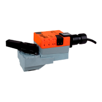
LMX24-MFT95
Proportional Control, Non-Spring Return, Direct Coupled, 24V, 0 to 135Ω Input
Accessories
K-LM20 3/4” [20 mm] Shaft Clamp
AV6-20 Shaft Extension
ZG-LMSA Shaft Adaptor for 1/2” Diameter Shafts
ZG-LMSA-1 Shaft Adaptor for 3/8” Diameter Shafts
ZS-100 Weather Shield - Steel
ZS-150 Weather Shield - Polycarbonate
Tool-06 8 mm & 10 mm Wrench
S1A, S2A Auxiliary Switch (es)
P370 Shaft Mount Auxiliary Switch
P…A Feedback Potentiometers
NSV24 US Battery Back-Up Module
ZG-X40 Transformer
Note: When using LMX24-MFT95 actuators, only use
accessories listed on this page.
®
1
2
3
5
4
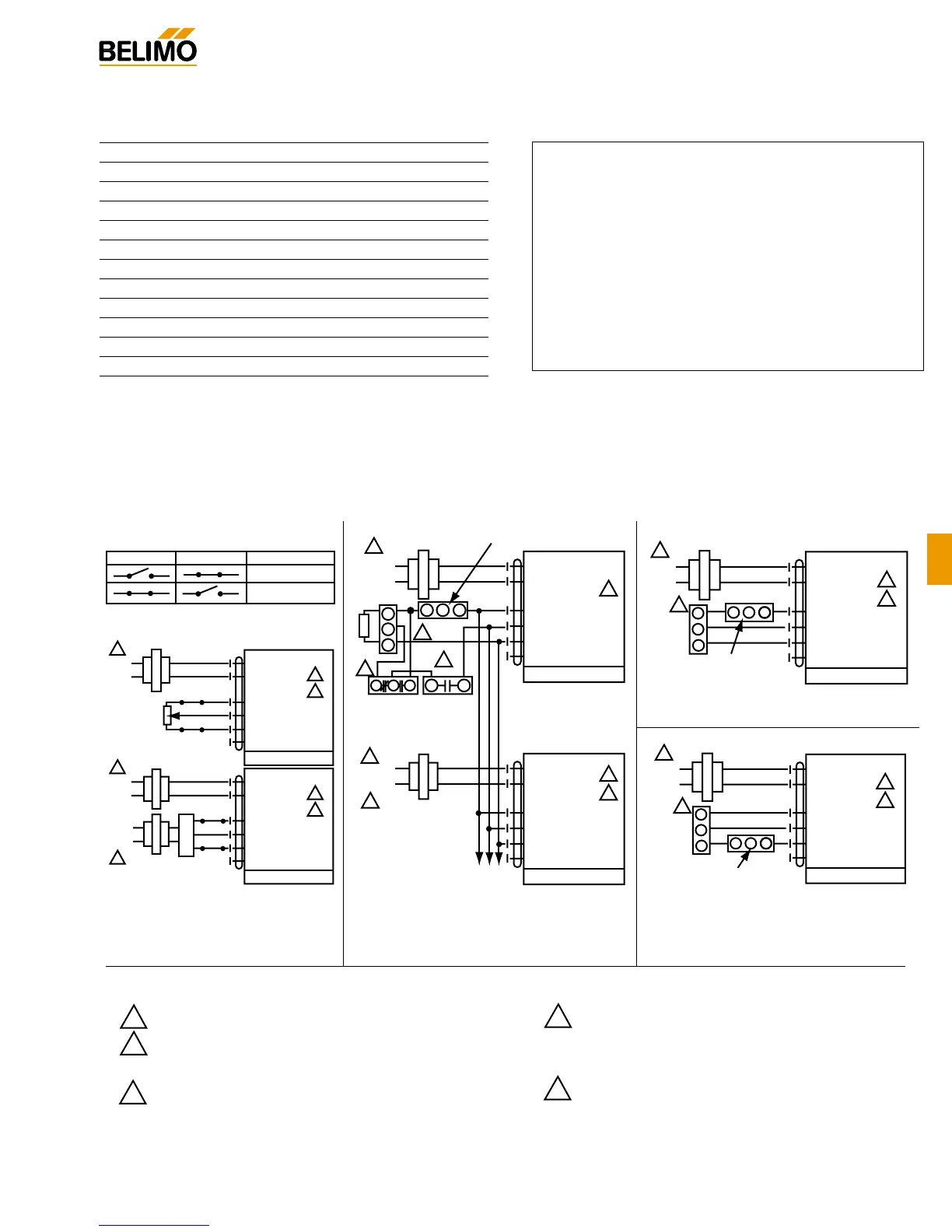
Provide overload protection and disconnect as required.
Actuators and controller must have separate transformers.
Consult controller instruction data for more detailed
installation information.
1
3
2
2
5
4
1 Common
2 + Hot
3 W
4 R
5 B
6 ‘U5’
Output 2-10 VDC
…MFT95
Line
Volts
24 VAC
Transformer
1
3
5
1 Common
2 + Hot
3 W
4 R
5 B
6 ‘U5’
Output 2-10 VDC
…MFT95
To other
actuators
Series 90
Controller
S963A
Minimum Position
Potentiometer
H205 Change-
over Controller
Occupied
Contact
Shunting
Resistor
Line
Volts
Wiring multiple actuators to a
Series 90 controller using a
minimum position
potentiometer.
Override
RB
W
B
R
W
W
R
B
Switch A Switch B Damper Position
Damper Open
Damper Closed
The direction of rotation switch is set so that the fail safe position and the
position of the damper is closed with no signal at wire R.
1
3
4
1 Common
2 + Hot
3 W
4 R
5 B
6 ‘U5’
Output 2-10 VDC
…MFT95
A
B
Line
Volts
24 VAC Transformer
135Ω
1
2
3
4
1 Common
2 + Hot
3 W
4 R
5 B
6 ‘U5’
Output 2-10 VDC
…MFT95
A
W
R
B
Controller
B
Line
Volts
Line
Volts
24 VAC Transformer
Low Limit Control
1
2
3
5
1 Common
2 + Hot
3 W
4 R
5 B
6 ‘U5’
Output 2-10 VDC
…MFT95
Line
Volts
24 VAC Transformer
WBR
W
B
R
R
Series 90 low limit control
135Ω for 0 to 50% control
280Ω for 0 to 100% control
Series 90
Controller
High Limit Control
1
2
3
5
1 Common
2 + Hot
3 W
4 R
5 B
6 ‘U5’
Output 2-10 VDC
…MFT95
Line
Volts
24 VAC Transformer
W B
W
B
R
R
Series 90 high limit control - 280Ω
Series 90
Controller
Resistor value depends on the type of controller and
the number of actuators. No resistor is used for one
actuator. Honeywell resistor kits may also be used.
To reverse control rotation, use the reversing switch.
Notes:
 Loading...