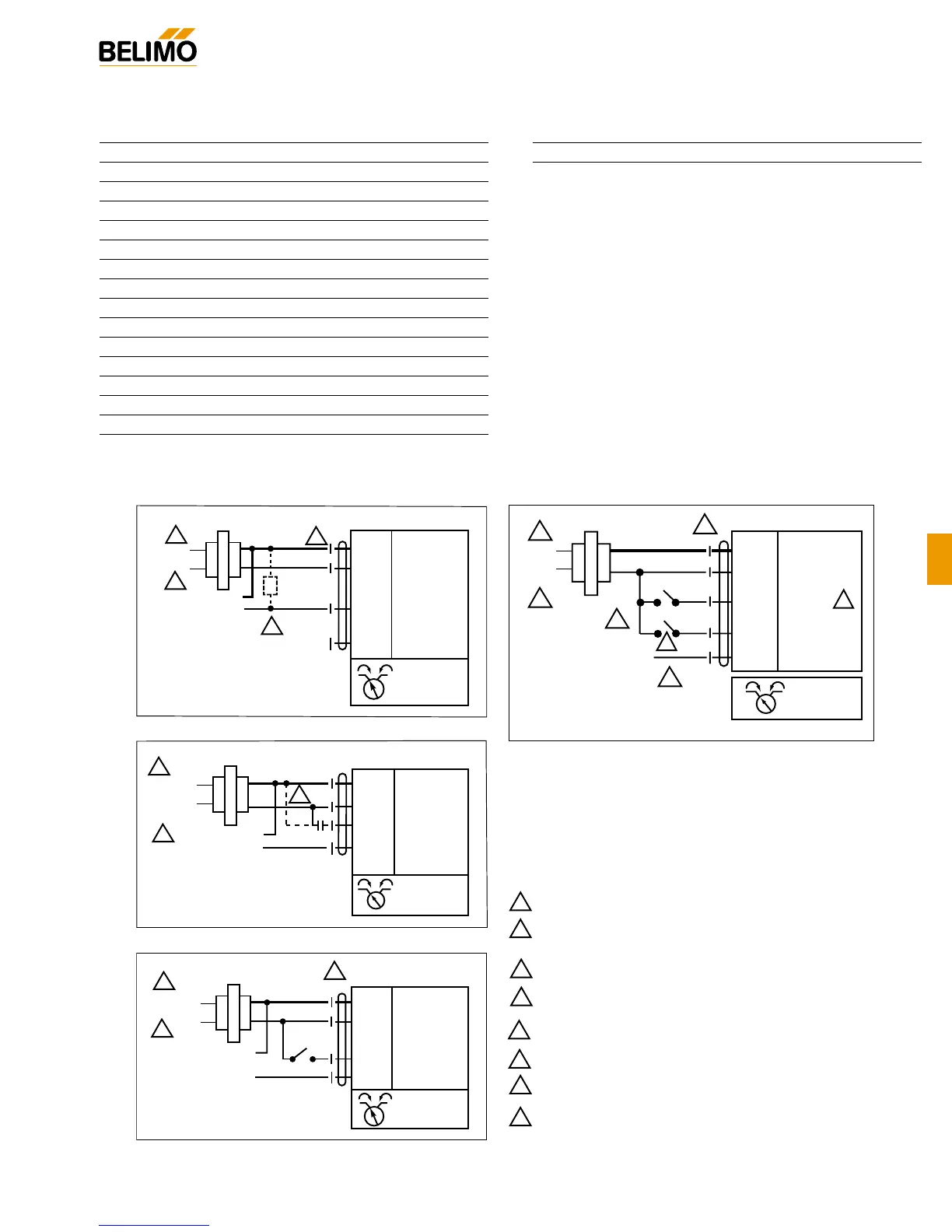
Wiring Diagrams
LMB(X)24-MFT - Typical Specification:
Proportional control damper actuators shall be electronic
direct-coupled type, which require no crankarm and linkage
and be capable of direct mounting to a shaft from 1/4” to 5/8”.
Actuators must provide control in response to a control input
from an electronic controller or positioner. Actuators shall have
Brushless DC motor technology and be protected from over-
load at all angles of rotation. Actuators shall have reversing
switch and manual override on the cover. Run time shall be
constant and independent of torque. Actuators shall be cULus
listed, have a 5-year warranty, and be manufactured under
ISO 9001 International Quality Control Standards. Actuators
shall be as manufactured by Belimo.
LMB (X) 24-MFT
Proportional Control, Non-Spring Return, Direct Coupled, 24V, Multi-Function Technology
®
Accessories
K-LM20 3/4” [20 mm] Shaft Clamp
AV6-20 Shaft Extension
ZG-LMSA Shaft Adaptor for 1/2” Diameter Shafts
ZG-LMSA-1 Shaft Adaptor for 3/8” Diameter Shafts
ZS-100 Weather Shield - Steel
ZS-150 Weather Shield - Polycarbonate
Tool-06 8 mm & 10 mm Wrench
S1A, S2A Auxiliary Switch (es)
P370 Shaft Mount Auxiliary Switch
P…A Feedback Potentiometers
SGA24 Min positioners in NEMA 4 housing
SGF24 Min positioners for flush panel mounting
ADS-100 Analog to Digital Switch
ZG-R01 Resistor for 4 to 20 mA Conversion
NSV24 US Battery Back-Up Module
1
2
Provide overload protection and disconnect as required.
Actuators may be connected in parallel if not mechanically mounted
to the same shaft. Power consumption and input impedance must
be observed.
3
Actuators may also be powered by 24 VDC.
Notes:
4
Position feedback cannot be used with a Triac sink controller.
The actuator internal common reference is not compatiable.
5
Control signal may be pulsed from either the Hot (Source)
or Common (Sink) 24 VAC line.
6
ZG-R01 may be used.
7
Contact closures A & B also can be triacs. A & B should
both be closed for triac source and open for triac sink.
8
For triac sink the common connection from the actuator
must be connected to the hot connection of the controller.
VDC/4-20 mA
6
Blk
(1) Common
Red
(2) + Hot
Wht
(3) Y
1
Input, 2 to 10V
Org (5) U Output, 2 to 10V
4 to 20 mA
or
2 to 10 VDC
Control Signal
Line
Volts
24 VAC Transformer
2
1
3
(+)
(–)
Ω
500Ω
1/4 watt
On/Off
Blk (1) Common
Red
(2) Hot
Wht
(3) Y Input
Org
(5) U Output
Line
Volts
24 VAC/DC Transformer
…MFT
a
Position
Feedback VDC
(+)
(–)
2
1
3
PWM
Blk (1) Common
Red
(2) + Hot
Wht
(3) Y Input
Org
(5) U Output
Line
Volts
24 VAC Transformer (AC only)
(+)
(–)
5
2
…MFT
…MFT
Position
Feedback VDC
1
Floating Point
…MFT
Line
Volts
2 to 10 VDC
Feedback Signal
24 VAC Transformer
Blk
(1) Common –
Red
(2) Hot +
Wht
(3) Y
1
Input
Pnk
(4) Y
2
Input
Org (5) U Output 2 to 10V
1
3
5
4
2
A
B
7
8
 Loading...