LMC24-SR Control and monitoring functions
10
Subject to technical changes / 01.00
Y
123
T
~
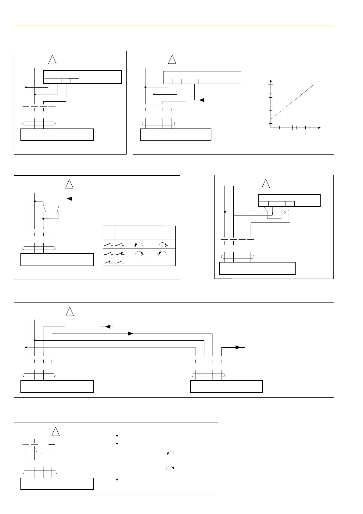
Remote control 0...100%
123
SGA24, SGF24
SGE24
Positioner
4
Y
T
~
Z
LMC24-SR
Parallel connection of further
actuators is possible (up to 10).
Y
123
T
~
123
SGA24, SGF24
SGE24
4
Y
T
~
Z
LMC24-SR
Minimum position
Y DC 0...10 V
(from controller)
100%
Angle of rotation
0%
Y [ V ]
10 V
min.
0 V
AC 24 V
5
U
5
U
AC 24 V
T
~
-
+
T
~
-
+
Parallel connection of further
actuators is possible (up to 10).
Positioner
!
Connect via
safety isolating
transformer
!
Connect via
safety isolating
transformer
Y
123
Override control
LMC24-SR
Parallel connecting of further actuators is
possible. Note power consumption data.
Y DC 0...10 V
a
b
5
U
ab
control mode
T
~
-
+
Reversing
switch R
Reversing
switch L
-
+
T
~
AC 24 V
DC 24 V
!
Connect via
safety isolating
transformer
Y
123
Position indication
LMC24-SR
5
U
T
~
AC 24 V
T
~
-
+
12
3
ZAD24
4
+
-
Direction of
rotation
!
Connect via
safety isolating
transformer
Y
123
Master-slave control (depending on position)
LMC24-SR
5
123
5
to next actuator
Master
actuator
Note ± 5% synchronism
tolerance between actuators
Slave
actuator
U
Y
LMC24-SR
U
T
~
-
+
T
~
-
+
Y DC 0...10 V
-
+
T
~
AC 24 V
DC 24 V
!
Connect via
safety isolating
transformer
Function monitoring
Y
U
LMC24-SR
123
T
~
AC 24 V
5
Procedure
AC 24 V at terminals 1 and 2
Disconnect terminal 3:
link terminals 2 and 3:
– actuator runs in the opposite direction
T
~
-
+
!
Connect via
safety isolating
transformer
– For direction of rotation "L":
actuator runs
– For direction of rotation "R":
actuator runs