VRP-M VAV
Adaptive VAV controller
14 / 28 Product information S4-VRP-M VAV • en • v2.0 • 11.2006 • Subject to changes www.belimo.eu
VRP-M Tool – Operating data settings
(Continued)
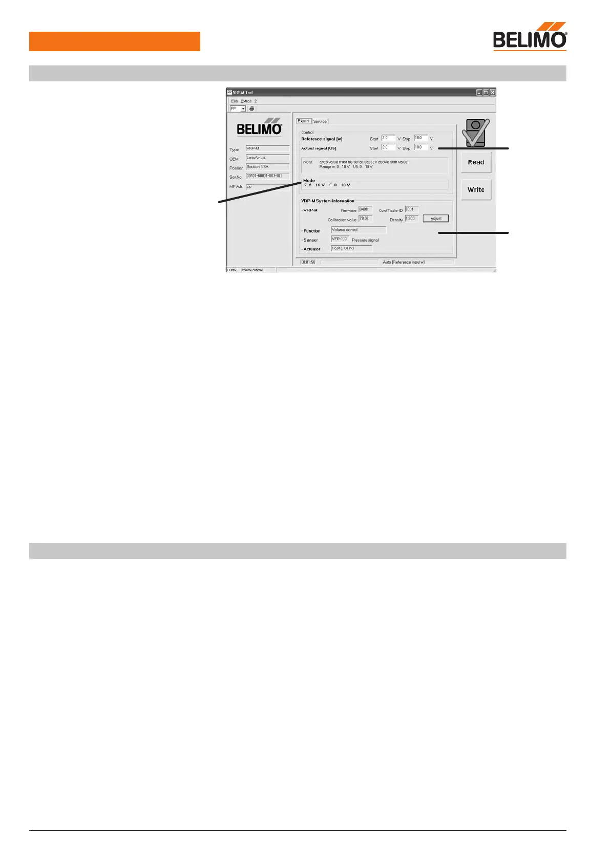
VRP-M-Tool
Expert tab
1 Mode setting
Standard 0 ... 10 / 2 ... 10 V
2 Control
System-specific settings
– Reference signal w
– Volumetric flow actual value signal U5
3 VRP-M system information
– VRP-M
Version and conductance setting
– Volumetric flow function
– Sensor type
– Actuator type
Mode setting
Options: 0... 10 V / 2...10 V / system-specific
The mode setting acts on the reference signal w and the volumetric flow actual value signal U5.
Variable settings are displayed here and can also be reset by selecting 2 ... 10 / 0 ... 10 V. Vari-
able settings are entered in the «Control» field above.
Control
Variable setting
It is sometimes essential to adapt the reference signal w or the volumetric flow actual value sig-
nal U5 to the MCR system directly on the control system.
The reference signal w and the volumetric flow actual value signal U5 can be set to different val-
ues (e.g. reference signal w: 2...10 V / actual value signal U5: 0...10 V).
Reference signal [w] / working range
min
...
max
Start point: DC 0.0 ... 8 V
Stop point: DC 2.0 ... 10 V
Volumetric flow actual value signal [U5] / display range 0...100%
nom
Start point: DC 0.0 ... 8 V
Stop point: DC 2.0 ... 10 V
1
2
3
VRP-M-Tool – Availability
The current version of the VRP-M-Tool and the associated documentation can be downloaded
from www.belimo.eu.