VRP-M VAV
Adaptive VAV controller
16 / 28 Product information S4-VRP-M VAV • en • v2.0 • 11.2006 • Subject to changes www.belimo.eu
Bus operation
The VRP-M system solution can be interconnected with other Belimo MP actuators (damper
actuators, valve actuators, VAV-Compact controllers, VRP-M system solutions) thanks to the
integrated communication principle over the Belimo MP-Bus. Up to eight Belimo MP devices are
supplied with a digital control signal by the higher-level bus master and then opened to the positi-
on dictated by this signal.
The switch-over from conventional to bus operation is automatic as soon as the MP actuator is
assigned an MP address (1...8).
Belimo MP devices can be integrated into the following systems:
– LONWORKS
®
: The variables of Functional Profile 8110 can be used in conjunction with the
Belimo UK24LON interface.
– EIB Konnex: Can be used with the Belimo UK24EIB interface
– DDC controller with an integrated MP-Bus protocol: Available from several manufacturers
Damper position (From VRP-M version V3.x)
(nvoAbsAngle - absolute actuator position in angular degrees (°))
The feedback signal, i.e. the network variable nvoAbsAngle, is not available for applications with
NM24-V-ST actuators (old actuator generation).
MP-Bus cycle time
The MP-Bus cycle time must be noted when integrating setpoints and actual values. It is typically
2...8 s, depending on the number of connected bus users and integrated sensors.
The local VRP-M control function is not affected by the cycle time. The cycle time of the MP-Bus
must always be taken into account, however, when selecting setpoints via the MP-Bus.
Mode of operation
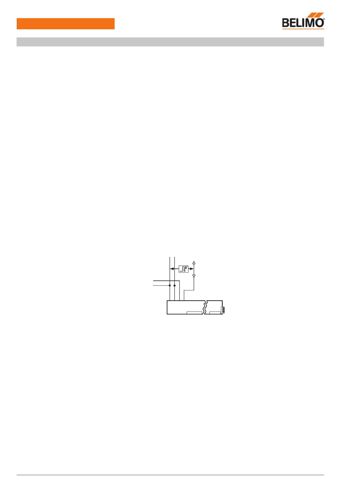
Sensor integration (From VRP-M version V3.x)
The VRP-M can be connected to an additional active 0 ... 10 V signal in MP-Bus mode inde-
pendently of the VAV control loop. The sensor signal is connected to the reference value input
that is not used in MP-Bus mode (connection 3).
The VRP-M then acts as an analogue/digital converter for transmitting the sensor signal to the
higher-level system. This system must know the physical address (which sensor is connected to
which MP device) and be capable of interpreting the corresponding sensor signal.
Active sensor connection
Active 0 ... 10 V sensors for open and closed-loop control functions in the higher-level system,
such as moisture or CO2 sensors. The cycle time must be taken into account in the implementation!
Reference signal w setting if an active sensor is connected: 0 ... 10 V
Integration of switches,
passive resistance sensors
The VRP-M only supports active sensors with a 0 ... 10 V output; i.e. no switches or passive
sensors (resistance elements) can be integrated.
Principle of VRP-M in bus operation
In bus operation, the VRP-M controller receives its reference signal from the higher-level control
system and adjusts the volumetric flow to the fixed selected value in the
min
...
max
range.
If necessary, the VAV
min
...
max
range can be overridden by fixed operating steps (control
inputs z1 and z2) in bus operation.
The following operating modes are available:
– Shut-off operation – damper CLOSED: The damper is moved into the CLOSED position in a
defined manner.
– Operating steps
mid
/
min
: The VRP-M adjusts the volumetric flow to the fixed selected value.
– Flushing operation – damper OPEN: The damper can be opened for maximum ventilation, in
which case air volume control is deactivated.
Sensor
 Loading...