VRP-M VAV
Adaptive VAV controller
www.belimo.eu Product information S4-VRP-M VAV • en • v2.0 • 11.2006 • Subject to changes 15 / 28
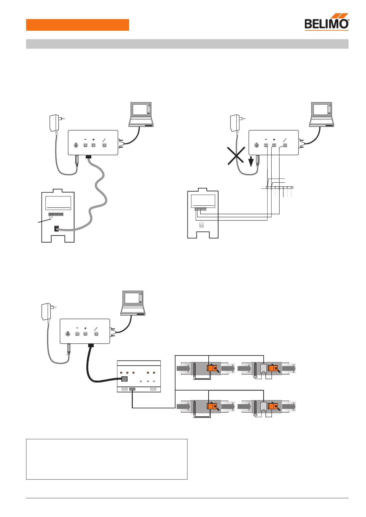
Connection of the VRP-M-Tool
The VRP-M-Tool required for settings and servicing can be connected either directly to the 3-pin service socket on the VRP-M controller or via
the MP connection (terminal 4). A level converter is required for communication, e.g.: ZIP-RS232.
Conventional operation (PP)
VRP-M runs with a locally connected reference signal (0 ... 10 V on connection 3). VRP-M detects that there is no tool connected and switches
back to the connected analogue reference signal automatically after 120 s.
VRP-M
AC 24 V
ZIP-RS232
1
2
5
OFF
Actuator
RS232
ON
U
PP
~
T
AC 230 V
ZN230-24
VRP-M
Tool
~
T
+
_
4.21
AC/DC 24 V
VRP-M
. . .
1
2
4
ZIP-RS232
1
2
5
OFF
Actuator
RS232
ON
U
PP
~
T
AC 230 V
ZN230-24
VRP-M
Tool
24 VAC
MP-Bus mode
VRP-M runs in the MP system, which means it obtains its reference signal via the connected MP master, e.g. UK24LON.
The VRP-M-Tool can only be connected via the bus master in MP mode, otherwise there would be two MP masters connected to the MP-Bus.
This means the local connection to the VRP-M cannot be operating at the same time as the MP master.
MP 1
MP-Bus
MP ..
UK24LON
2
MP 8
MP ..
AC 24 V
ZIP-RS232
1
2
5
OFF
Actuator
RS232
ON
U
PP
~
T
AC 230 V
ZN230-24
VRP-M
Tool
-
+
-
+
Note
• The service plug integrated in the VRP-M is not available with bus operation.
• The MP-Bus cannot be used to transmit control functions if it is also used to
connect the VRP-M-Tool.
Workaround: Disconnect the MP-Bus (terminal 4) and use the local MP plug
instead.
AC/DC
24 V
Connection in control cabinetConnection via service socket
LON application with UK24LON