• The controller is not allowed to be used outside the specified field of application, especially
in aircraft or in any other airborne means of transport.
• The device does not contain any parts that can be replaced or repaired by the user.
• The manufacturer of the VAV unit (OEM) is responsible for ensuring that the VRP-M-
controller is installed and set correctly as well as for the overall precision of the VAV unit. If
replacement devices are ordered, they are configured by the OEM at the factory according to
the installed system.
The VRP-M controller is sold exclusively via the OEM channel for this reason.
• The device contains electrical and electronic components and is not allowed to be disposed
of as household refuse. All locally valid regulations and requirements must be observed.
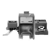
Application
Together with the VFP-.. static pressure sensor and a Belimo NM..-ST actuator, the VRP-M
forms a control system for pressure-independent variable (VAV) and constant (CAV) air volume
controls.
For more information, see «VRP-M system», pages 3 ... 6
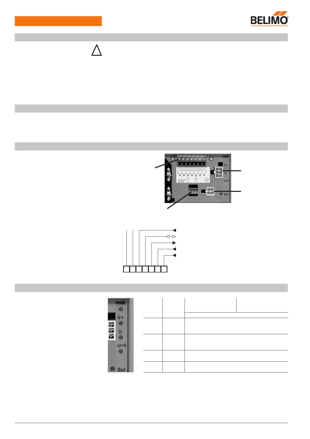
Electrical connections
Front panel
Assignment of terminals 1 ... 7
Terminals 1 ... 7
for supply and control
Tab connection for
damper actuator
Tab connection for
pressure sensor
Diagnostics socket for VRP-M-Tool
VAV reference signal
min
...
max
PP/MP signal
Volumetric flow actual value 0 ... 100%
nom
OPEN operating step
CAV operating step CLOSED /
min
/
mid
/
max
LED indicator and address pushbutton
PWR Green LED LED on:
– AC/DC 24 V supply OK
– Device ready
LED off:
– Supply failure
– Device defective
Blinking
– If Set pushbutton pressed during MP adressing
+ Red LED LED on:
– Volumetric flow > setpoint = damper closes
or is closed
– Red LED LED on:
– Volumetric flow < setpoint = damper opens
or is open
∆p>0 Yellow LED Zero offset of VFP-.. pressure sensor
(refer to page 6 for procedure)
Set Pushbutton for assigning MP address in bus operation
(refer to page 18 for procedure)