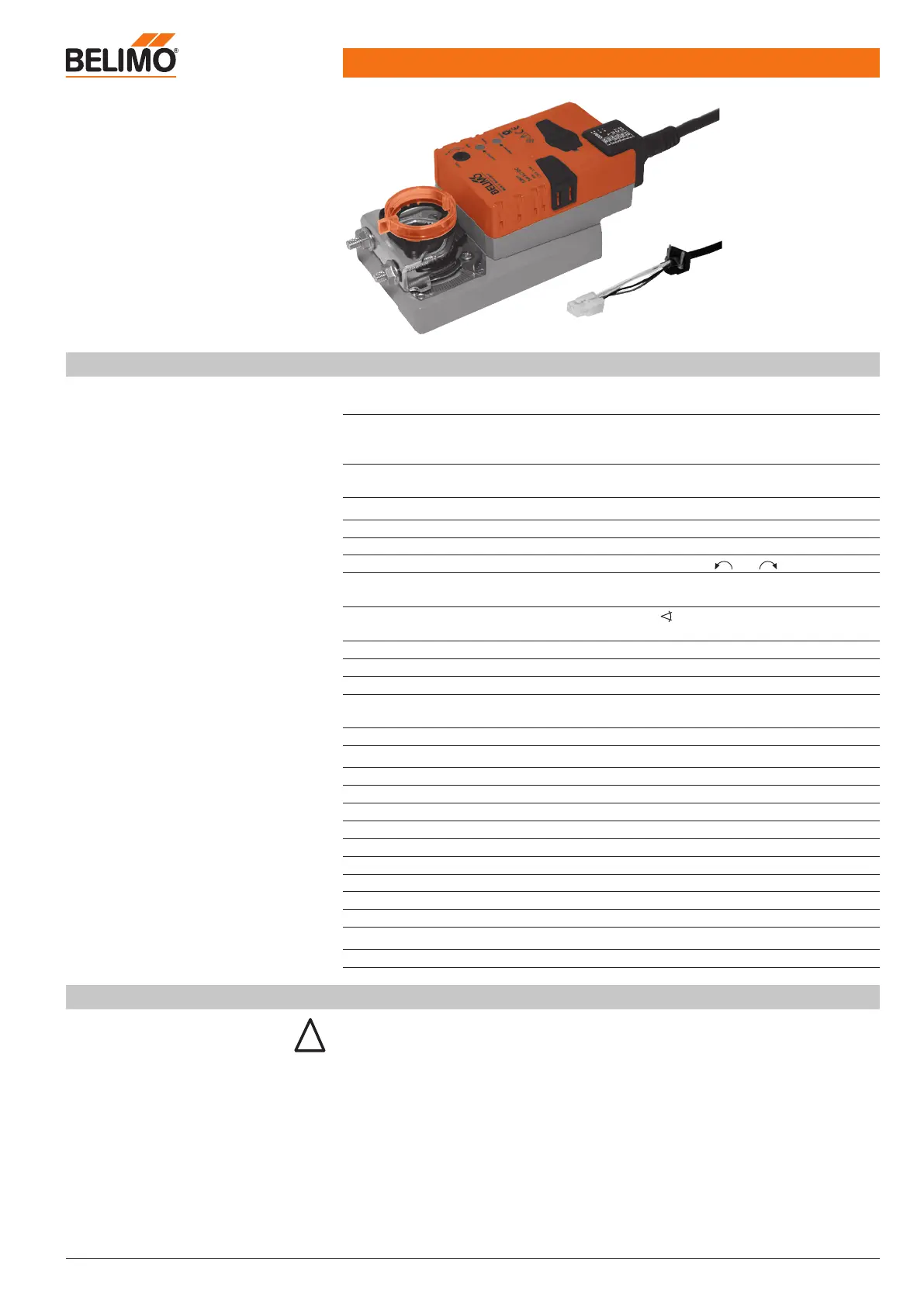
Technical data sheet NM24A-V-ST actuator
www.belimo.eu Product information S4-VRP-M VAV • en • v2.0 • 11.2006 • Subject to changes 23 / 28
Damper actuator
for VRP-M system solution
Technical data
Electrical data
Nominal voltage AC 24 V, 50/60 Hz / DC 24 V
(from VR.. controller)
Power consumption In operation
At rest
For wire sizing
3.5 W @ nominal torque
1.25 W
5.5 VA
Connection 0.5 m cable with 6-pin plug
(compatible with VRP-M)
Functional data
Torque (nominal torque) Min. 10 Nm @ nominal voltage
Uni-rotation ±5%
Direction of rotation Can be selected with 0 / 1 switch
Direction of motion at Y = 2 V In switch position 0 or 1
Manual override Disengaging the gearing latch by means
of a pushbutton, self-resetting
Angle of rotation
Max. 95° , can be limited at both ends
with adjustable mechanical end stops
Running time 150 s
Sound power level Max. 35 dB (A)
Position indication Mechanical, plug-on
Adaptation Adaptation of the control range
to the damper angle of rotation
Display LED display for 24 V supply and states
Safety
Protection class III Safety extra-low voltage
Degree of protection IP54 in all mounting positions
EMC CE according to 89/336/EEC
Mode of operation Type 1 (in acc. with EN 60730-1)
Rated impulse voltage 0.8 kV (in acc. with EN 60730-1)
Control pollution degree 3 (in acc. with EN 60730-1)
Ambient temperature range –30 ... +50°C
Non-operating temperature range –40 ... +80°C
Ambient humidity range 95% RH, non-condensating (EN 60730-1)
Maintenance Maintenance-free
Dimensions/weight
Dimensions See «Dimensions» on page 25
Weight Approx. 710 g
Safety notes
• The damper actuator is not allowed to be used outside the specified field of application,
especially in aircraft or in any other airborne means of transport.
• It may only be installed by suitably trained personnel.
All applicable legal or institutional installation regulations must be complied with.
• The device may only be opened at the manufacturer‘s site. It does not contain any parts that
can be replaced or repaired by the user.
• The cable is not allowed to be removed from the unit.
• When the required torque is calculated, the cross section, design and installation site as
well as the air flow conditions must be observed.