VRP-M VAV
Ready-to-connect system solution
6 / 28 Product information S4-VRP-M VAV • en • v2.0 • 11.2006 • Subject to changes www.belimo.eu
Commissioning
Prerequisites
– The VAV / CAV unit must be mounted
– The VRP-M system solution must have been set and calibrated for the VAV / CAV unit by the
unit manufacturer
– The electrical connection must have been made and checked
– The 24 V supply and control must be ready for operation
– The system fan must be in operation
Procedure
– Check the electrical connection
– Check the zero offset of the pressure sensor
– Check the damper mobility
– Check the supply pressure (the system fan must be in operation and calibrated)
– Check the
min
/
max
settings and correct them if necessary
– Check the control signal setting and adjust it if necessary
Angle of rotation adaptation
The angle of rotation must be adapted whenever the angle of rotation limiting of the
NMQB24-SRV-ST damper actuator is adjusted.
Procedure:
– Switch on the 24 V supply
– Press the manual override pushbutton twice
The actuator moves into the CLOSED...OPEN...setpoint position
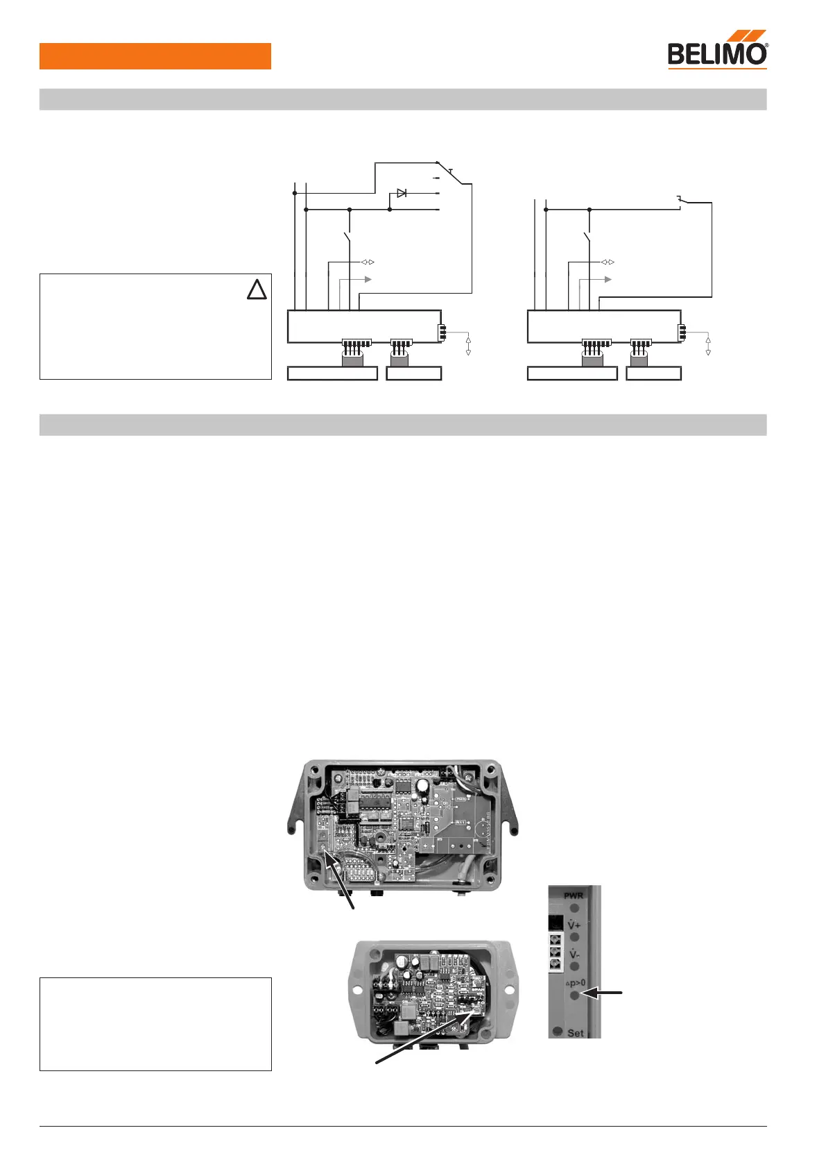
VFP-.. static pressure sensor
Zero offset
– Disconnect both (!) hose connections from the
sensor
– Remove the cover of the VFP-.. sensor
housing
– Turn the zero potentiometer inside the VFP‐..
until the LED in the VRP-M [p>0] lights up
– Turn the zero potentiometer back until the LED
goes out again
Zero potentiometer VFP-100
Note
Fast-running damper actuator NMQB24-SRV-ST
A synchronisation is performed after the power sup
-
ply is switched on or after the manual disengage
-
ment is actuated; this means the actuator moves to
CLOSED and returns to its nominal position.
Zero potentiometer VFP-300
VFP-600
Electrical installation
(Continued)
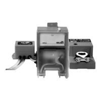
Wiring diagrams: CAV operation Example 1: Example 2:
min
–
max
– OPEN
See pages 10 and 11 for a description of function
Note
– Supply via safety isolation transformer!
– We recommend routing connections 1, 2
(AC/DC 24 V), 4 (MP signal) and 5 (U5 signal)
to accessible terminals (floor distributor, control
cabinet, etc.), in order to simplify access with the
VRP-M-Tool for diagnostic and service work.