OPERATION
OPERATING COMPONENTS
Internal Components
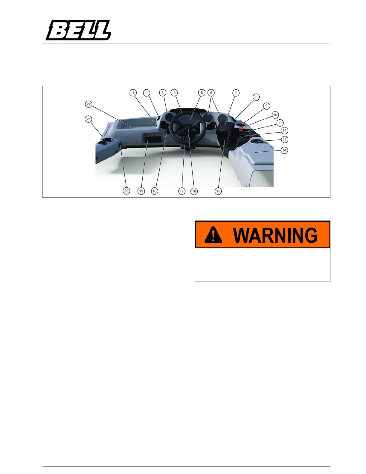
Operator's Station
1. 12V Accessories Socket
2. Air Vent
3. Air Vent
4. Steering
5. Colour Display Unit
6. Air Vent
7. Sealed Switch Module (SSM)
8. Air Vent
9. Cup Holder
10. Emergency Stop Button
11. Rear-view Mirrors Adjustment Switch (Optional)
12. B-Drive
13. Air Vent
14. Cooler Box
15. Bonnet Switch
16. Steering Wheel Telescopic adjustment
17. Steering Wheel Adjustment Lever
18. Steering Column Switch
19. Radio/CD player (optional)
20. Cigarette Lighter Socket
21. Cup Holder
22. Fuse/Relay and Diagnostic Socket
Compartment
Steering Wheel
If there is an engine or main pump failure, the ground
driven emergency steering system will enable the
operator to steer the machine to a safe stop.
In this event the machine must be stopped as quickly
as possible.
There is no self-centralising action on the steering.
The machine must be returned to the straight
ahead position by turning the steering wheel.
The steering wheel can be adjusted to ensure
maximum operator comfort.
 Loading...