OPERATION
OPERATING COMPONENTS
2. Before activating the Over Centre Bin Lock,
prepare the truck for maintenance. (Refer to
chapter "Maintenance Safety Precautions" for
the procedure)
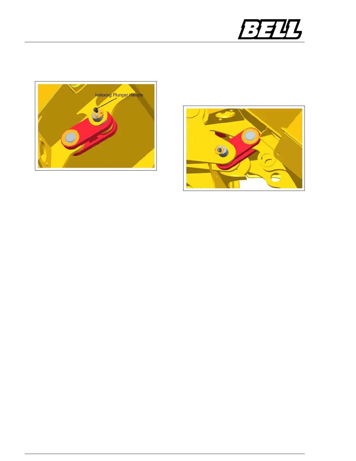
Figure 1: Over Centre Bin Lock Feature
(Male Clevis)
3. Start the engine and tip the bin to the maximum
tipping angle. The male clevis of the Over
Centre Bin Lock will engage with the female
clevis in the rear chassis.
NOTE
Ensure that there is no one in close
proximity to the moving bin.
4. Once the bin has reached to maximum tip an-
gle, switch the engine off and proceed to install
the Over Centre Bin Lock.
5. While the engine is switched off, remove the pin
from its stowage position. This is done by pull-
ing on the indexing plunger handle and rotating
the locking disc counter-clockwise so that the
disc becomes concentric to the pin and the in-
dexing plunger lands on the corresponding in-
dexing hole in the pin (Refer to Figure 1 ). The
pin can now be withdrawn.
6. Insert the locking pin through the holes in the
chassis and the Over Centre Bin Lock (Refer to
figure 2).
7. Should the holes not be aligned, repeat step 3
by adjusting the tip angle accordingly to align
the holes and then proceed with steps 4 - 6.
8. Pull the indexing plunger handle and turn the
locking disc clockwise to an eccentric position,
thus preventing the pin from being removed.
Allow the indexing plunger to engage in the ap-
propriate hole in the pin.
9. A lock-out device can be inserted into the hole
provided on the locking disc when the Over
Centre Bin Lock is engaged. (Refer to "Lock-
Out Point" in chapter "General Service Informa-
tion" for the procedure.)
Figure 2: Over Centre Bin Lock in Activated
Position
Removing the Over Centre Bin Lock
1. When the machine service is complete, Start
the engine and raise the bin to relieve pressure
form the locking pin.
2. Switch the engine off and proceed to remove
any lock-out device from the hole in the locking
disc.
3. Remove the locking pin, following the same
procedure with the indexing plunger and locking
disc as that used when activating the lock.
4. Start the engine and lower the bin fully.
NOTE
: Ensure that there is no one in close
proximity to the moving bin.
5. Insert the locking pin in its stowage location.
6. Pull the indexing plunger handle and turn the
lockingdiscclockwisetoaneccentricposition,
thus preventing the pin from being removed. Al-
low the indexing plunger to engage in the ap-
propriate hole in the pin.

 Loading...