OPERATION
OPERATING INSTRUCTIONS
BinLoweringProcedureAfter
Engine/Pump Failure
Emergency bin lowering will be required in the case
when there is a major machine failure where the bin
cannot be lowered by the normal operator bin function
controls.
Inspect the terrain and surrounding areas where the
machine has failed to establish if it is safe to continue
with this procedure.
Ensure there are no overhead lines that might
interfere with the bin movement.
Ensure people and other processes or operations are
clear from the machine when commencing with the
emergency bin lowering.
If possible, engage the artic lock.
Always ensure that cab is not in the raised position
when lowering the bin. It could be required in this
procedure that the cab needs to be raised.
Do not loosen any hoses, connectors or fittings
unless the emergency bin lowering procedure
indicates otherwise.
Tools and Equipment Required
• 18 mm spanners (to loosen the cab bolts)
• 30 mm spanner
• 5 mm Allen key
• Hydraulic hand Pump
Procedure:
1. Inspect and examine the machine and the sur-
rounding area where the machine has failed to
determine if it is safe to commence with the
emergency bin lowering. Ensure nothing will in-
terfere with the bin movement when lowering
the bin. Ensure all people are cleared from the
machineandbinarea.
2. Install the artic lock if possible and place wheel
chocks on two wheel sets either side of the ma-
chine. Also ensure the cab is not in the raised
position when commencing with step 7 of this
procedure.
3. If the bin is stuck in a position where the tip cyl-
inders are not fully extended and the bin is not
over centre on the bin pivots, steps 4 to 5 of this
procedure could be left out and proceed with
step 6. If the tip cylinders are fully extended and
the bin is over the centre of the pivot points, a
hand pump will be required to assist with the
lowering of the bin.
4. Use the 30mm spanners to loosen the cab
bolts. Raise the cab and ensure the cab tilt lock
is engaged.
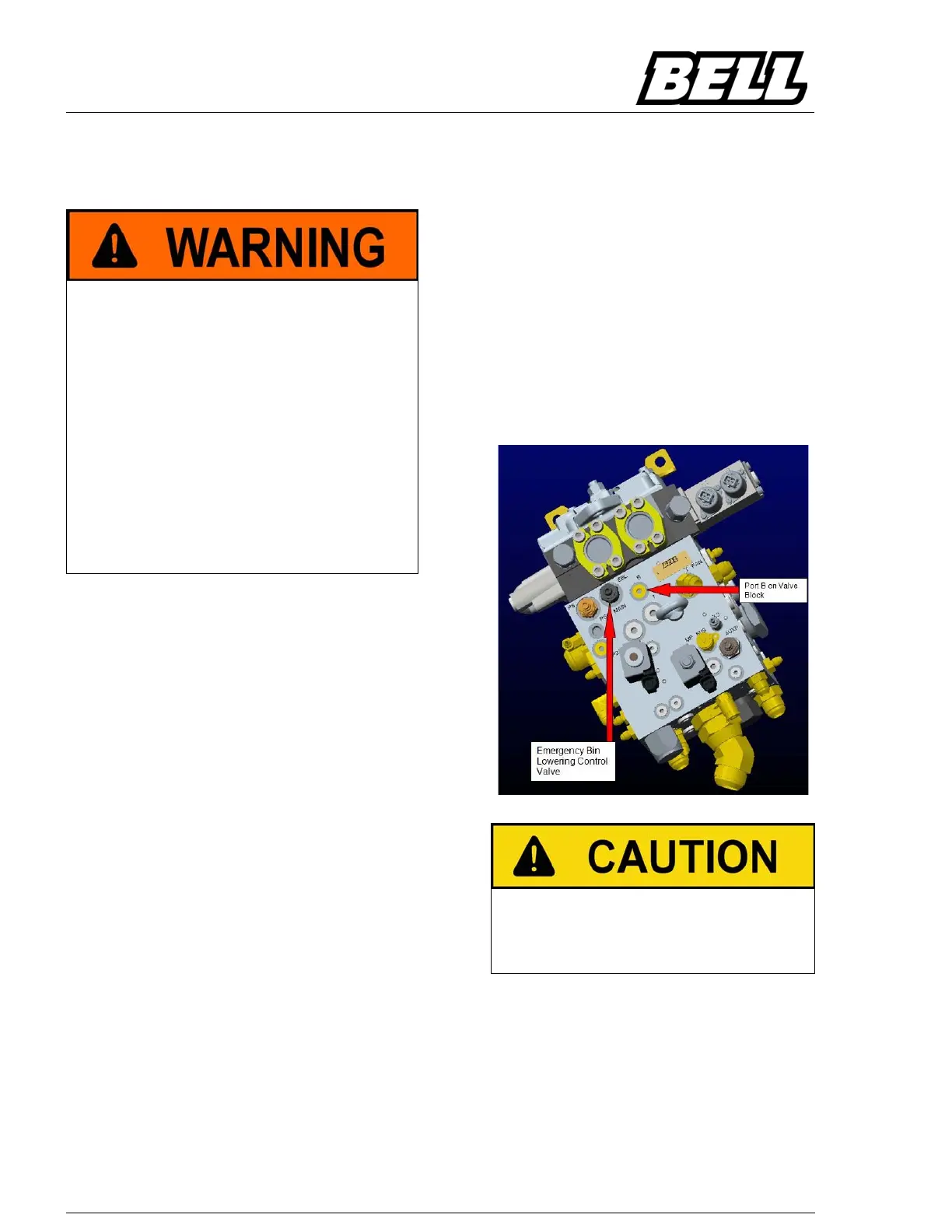
5. Remove the plug on port B from the tip valve
block (1/4” Allen Key). Connect the hose of the
hand pump to port B. The hand pump will be
used to jack the bin back over the center point
of the bin pivots. The weight of the bin will then
be used to lower the bin by controlling the
emergency bin lowering control valve situated
on the side of the tip valve block. Ensure to
place the hand pump in a safe area next to the
machine, clear from the rear chassis and bin of
the machine.
6.
Before continuing with step 7 of this procedure, en-
sure the cab is in the lowered position and the front
chassis and rear chassis are in a straight position,
so when the bin is lowered the bin does not connect
with the cab.
7. Use the 18mm spanner to loosen the lock nut
of the emergency bin lowering control valve.
This valve is situated on the top face of the tip
valve block.
8. Use the 5mm Allen key and slowly turn the
emergency bin lowering control valve counter
clockwisetoopenthevalveforthebintocome
down. The more turns counter clock wise the
faster the bin will lower. If a hand pump is con-
nected to assist with the bin lowering, open the
 Loading...