19
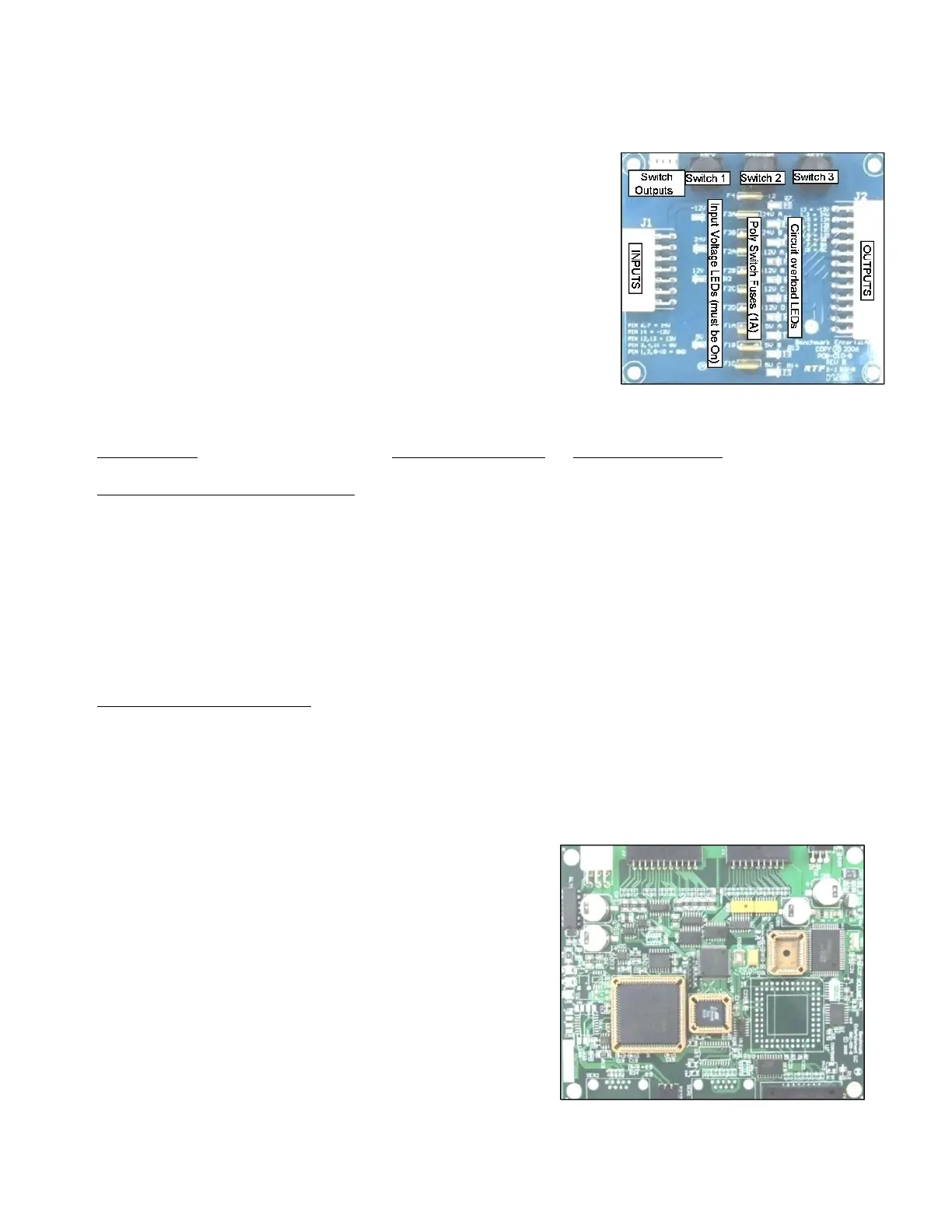
Power Distribution Board
Part# 500PCB032
Qty: 1
Location: Control Panel.
ID-Switch setting: None, board has no computer.
Distributes DC power from the power-supply to the different devices,
through a Poly-Switch (thermal, resettable fuse) for each voltage circuit.
Not that for convenience, the ‘Programming Options’ Buttons are also
located on this board, even though they’re not power-related.
Power is distributed in the following manner (worst case estimations):
BOARD/DEVICE Estimated consumption Fuse circuit (see board)
POWER DISTRIBUTION BOARD CIRCUITS:
Sound Board, Quad-Stepper 2.A 24v [A]
Solenoids, Jackpot display 1A 24v [B]
IO-Expander 1 (Logic) 0.4A 12v [A]
P1 Ticket-dispenser, reload button, door (coin-mech.) 1A 12v [B]
P2 Ticket-dispenser, reload button, door (coin-mech.) 1A 12v [C]
P1 playfield-lights & marquee, P2 playfield-lights 4A 12v [D]
Player1 4-digit display 0.2A 5v [A]
Main board (logic) 0.2A 5v [B]
Player2 4-digit display 0.2A 5v [C]
DEDICATED ‘PIGTAIL’ TERMINALS:
Inner/Lower Marquee 1.5A 12V pigtail (5 Amp Fuse)
Outer/Upper Marquee 0.5A 24V pigtail (5 Amp Fuse)
Related Note: There are 2 AC fuses on the Power supply IEC-130 receptacle (10Amp, 250 V).
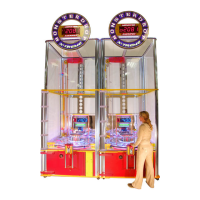
Main CPU Board (BMC-001-B)
Part# 116PCB001
Qty: 1
Location: Control Panel.
ID-Switch setting: None Master board needs no ID.
This board is the main controller of the game. It decides all the
game actions and commands the other boards to act according
to the game scheme.
Communication to the other boards is performed via a 485
differential wire-pair (Gray and blue wires).
The ‘Programming Mode’ game-settings information is saved in
an on-board FRAM chip.