9
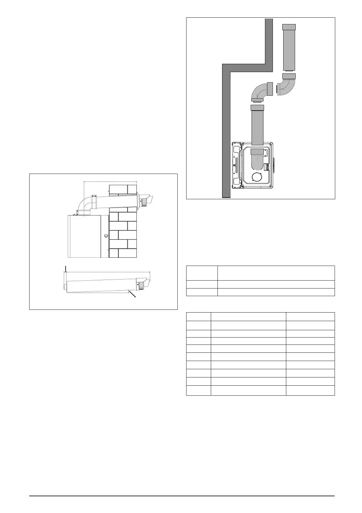
Fig. 9A
FITTING THE HORIZONTAL FLUE KIT
Carefully measure the distance from the centre of
the appliance flue outlet to the edge of the finished
outside wall (dimension X). Add 65mm to dimen-
sion X to give you Dimension Y (see fig 9A).
Measure dimension Y from the terminal end of the
concentric flue pipe and cut off the excess ensur-
ing any burrs are removed. Pass the concentric
flue pipe through the previously drilled hole. Fit the
flue bend to the boiler flue outlet and insert the
concentric flue pipe into the flue bend ensuring the
correct seal is made. Using the clamp, gasket,
and screws supplied, secure the flue bend to the
appliance flue spigot.
NOTE
Fit the internal (white) trim to the flue assembly
prior to connecting the flue pipe to the bend.
You must ensure that the entire flue system is
properly supported and connected. Seal the flue
assembly to the wall using cement or a suitable
alternative that will provide satisfactory weather-
proofing. The exterior trim can now be fitted.
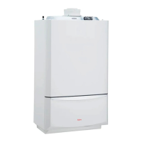
4.5.1.1 EXTENDING THE FLUE
Connect the bend – supplied with the terminal kit
– to the top of the boiler using clamp (supplied)
see fig. 9. The additional bends & extensions have
push-fit connections, care should be taken to en-
sure that the correct seal is made when assem-
bling the flue system. Connect the required number
of flue extensions or bends (up to the maximum
equivalent flue length) to the flue terminal (see
fig. 9 & 10). The flue system should have a mini-
mum of 1º; maximum of 3º rise from the boiler to
outside, to ensure any condense fluid that forms,
is allowed to drain back to the appliance.
NOTE
When cutting an extension to the required length,
you must ensure that the excess is cut from the
plain end of the extension (see fig. 9 & 10). Re-
move any burrs, and check that all seals are lo-
cated properly. You must ensure that the entire
flue system is properly supported and connected.
Seal the flue assembly to the wall using cement
or a suitable alternative that will provide satisfac-
tory weatherproofing. The interior and exterior trim
can now be fitted.
4.5.2 CONCENTRIC VERTICAL FLUE
The vertical flue terminal can be connected directly
to the appliance flue outlet. Alternatively, an exten-
sion or bend can be connected to the appliance flue
outlet if desired (see 4.4.2), however if additional
bends are fitted, a reduction must be made to the
maximum flue length (see table below).
Reduction for bends
Bend Reduction in maximum flue length for each
bend
45º bend 0.5 metre
90º bend 1.0 metre
Vertical flue terminal and accessories
Part No. Description Min-Max Length
490 Vertical flue terminal
497 Pitched roof flashing plate N/A
498 Flat roof flashing plate N/A
492 0.5m extension 500 mm
493 1.0m extension 1000 mm
494 2.0m extension 2000 mm
495 45º bend (pair) N/A
496 90º bend N/A
499 Wall bracket N/A
Using the dimensions given in fig. 9 as a reference, mark
and cut a 115mm hole in the ceiling and/or roof.
“X”
“Y”
30mm
1-3 degree
“X” + 65mm = “Y”
Fig. 10