23
8.1 EXTERNAL WIRING
The appliance comes with a factory fitted (TA)
link to allow basic operation of the boiler via the
mode selector switch. If external controls are to
be added to the system, they must be connected
to the appliance as shown in the following dia-
grams. For advice on controls that are not fea-
tured in this book, please contact the Service &
Technical Helpline on 0870-264-1220.
8.1.1 EXTERNAL WIRING LIMITATIONS
Any external wiring must remain within the limits
as detailed in the table below:
CONNECTION MAX. LENGTH
External sensor 30-metres
Room thermostat 30-metres
OT+ connection 30-metres
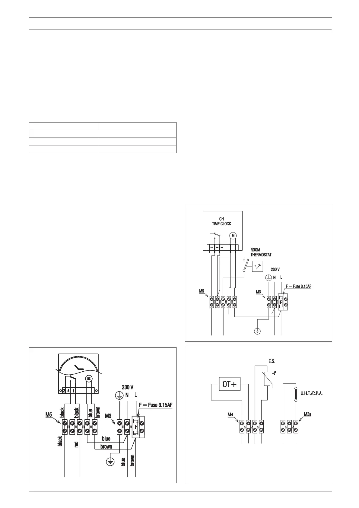
8.2 TYPICAL CONTROL APPLICATIONS
The appliance can be used with the following con-
trols:
• programmable room thermostats (fig. 40).
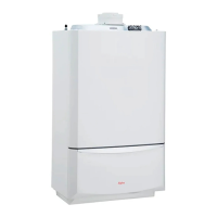
• OT+ control, please contact the technical for
detailed instruction on specific OT+ controls
(fig. 41).
• external sensor.
8.3 OTHER DEVICES
Contact the controls manufacturer and/or the
technical department should you require more
specific information on the suitability of a particu-
lar control. Further guidance on the recommended
practice for the installation of external controls,
can be found in CHeSS – HC5/HC6
(www.energyefficiency.gov.uk).
SECTION 8 WIRING DIAGRAMS
8.4 MECHANICAL CLOCK
A mechanical clock is fitted for the Procombi A
range and eliminates the need for an external time
control.
Fig. 41
U.H.T. = underfloor heating thermostat
C.P.A.= condensate pump alarm
E.S.= external sensor
OT+= opentherm + connection
OPTIONAL DEVICE (24V) TERMINAL BLOCK
Fig. 40
IMPORTANT
• The boiler must always be supplied with a per-
manent 230V electrical supply.
• Always remove the link between TA & TA on the
appliance high-voltage terminal strip whenever
additional controls are connected to the appli-
ance.
• Do not connect any controls or auxiliary equip-
ment to the low-voltage terminal strip, other than
that approved/supplied by the manufacturer.
Fig. 39