24
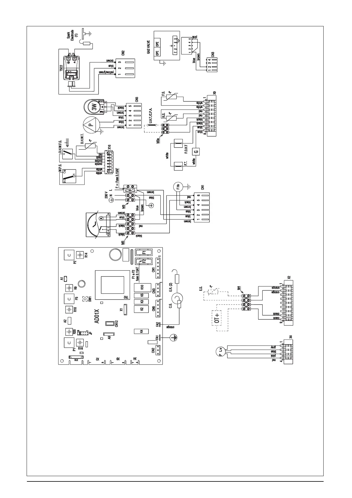
FUNCTIONAL DIAGRAM
Fig. 38
NOTE: L-N-E connection is advisable
F Hv Fan power supply 230 V
F Lv Fan signal control
P Pump
F Fuse 3.15A F (fast)
F1-F2 Fuse 3.15A T (delay)
OPE Gas valve solenoids
S.E. (1) Spark electrode
S.E. (2) Sense electrode
C.S. Condensate sensor
G.V. Gas valve
TSC2 Ignition transformer
TR2 PCB transformer
E.S External sensor
WPS Water pressure switch
FS Flow thermistor (NTC)
RS Return thermistor (NTC)
AD01X Main PCB
CN1÷CN5 Connection to PCB high voltage
X2÷X16 Connection to PCB low voltage
F.O.H.T Flow over heat thermostat
F.T Fume thermostat
G Cable connector
M3-M5 Terminal strip for supply in / clock / room thermostat
M3a-M4 Terminal strip for esternal sensor / condense pump / low temperature
thermostat
OT+ Open therm + connection
D.H.W.F.S Domestic hot water flow switch
D.H.W.T Domestic hot water temperature
3W 3 way motor
JP5 For combi boiler
X1 Connector minitank (unused)
CN12 Service connector
SW1 Co button
A1 24V output to 2CH - programmer
P1 DHW potentiometer
P2 Heating potentiometer
P3 Selector switch
R9 Trimmer for maximum output
R10 Trimmer for minimum output
R14 Trimmer for ignition fan speed
R19 Trimmer for heating fan speed
R35 Trimmer thermoregulation
UHT Underfloor heating thermostat
CPA Condensate pump alarm