30
SECTION 10 LPG INSTRUCTIONS
10.1 RELATED DOCUMENTS
BS 5440 PARTS 1 & 2 FLUES & VENTILATION REQUIREMENTS
BS 5449 PART 1 FORCED CIRCULATION OF HOT WATER SYSTEMS
BS 5482 PART 1 DOMESTIC BUTANE & PROPANE GAS BURNERS IN PERMAMENT
DWELLINGS
BS 5546 INSTALLATION OF GAS HOT WATER SUPPLIES FOR DOMESTIC
PURPOSES
BS 6798 INSTALLATION OF BOILERS OF RATED NOT EXCEEDING 60kW
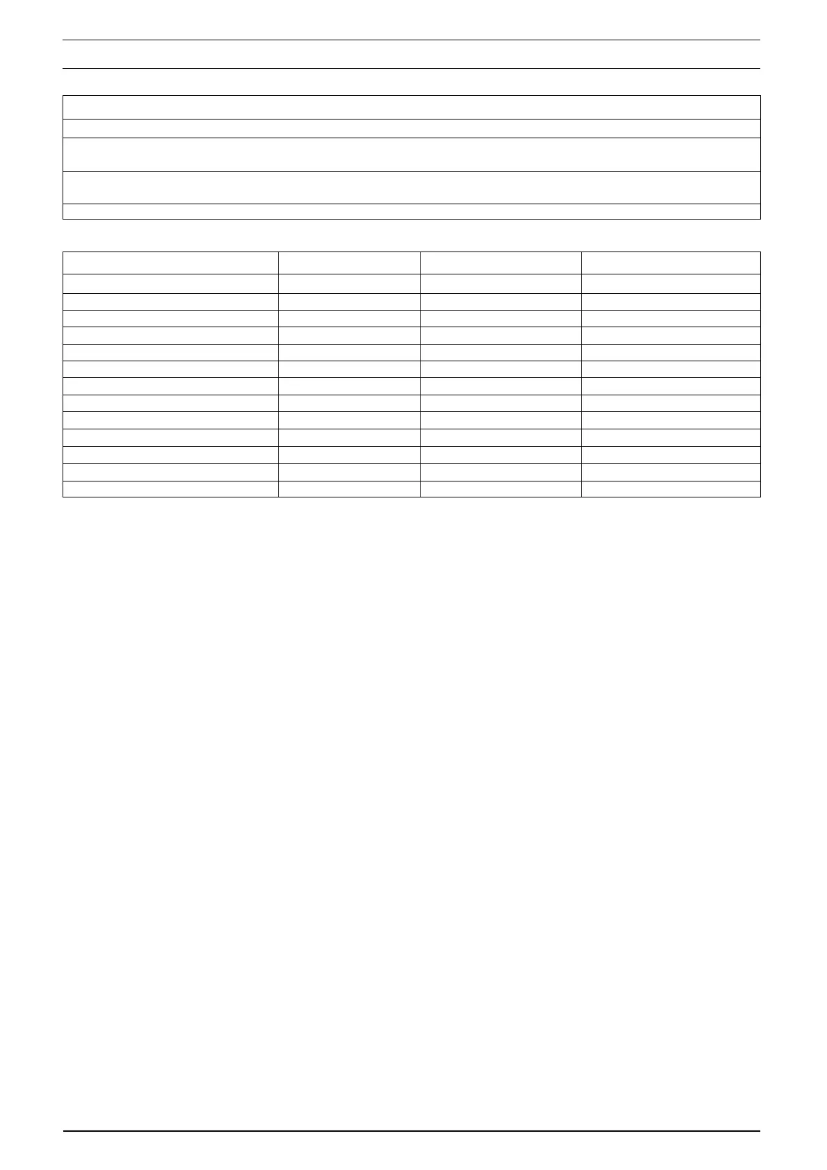
10.2
Gas Pressures Procombi A28 Procombi A32 Procombi A36
Inlet pressure 37.0mbar
Maximum gas rate (kg/hr) 2.17 2.48 2.80
Minimum gas rate (kg/hr) 0.47 0.54 0.54
Injector size 4.7mm 4.7mm 5.0mm
CO
2
max (%) 10.0 10.0 10.0
CO
2
min (%) 10.0 10.0 10.0
CO max (mg/kWh) 182.8 215.0 236.5
CO max (mg/kWh) 32.3 21.5 21.5
NOx max (PPM) mg/kWh 70.6 88.3 8.3
NOx min (PPM) mg/kWh 53.0 53.0 70.6
CO/CO
2
ratio @ max 0.002 to 1 0.002 to 1 0.002 to 1
CO/CO
2
ratio @ min 0.004 to 1 0.004 to 1 0.004 to 1
SEDBUK ‘A’ (%) 92.4 2.7 92.7
10.3 CONVERTING THE APPLIANCE GAS TYPE
To convert the appliance to another gas type it is
necessary to change the burner injector, adjust
the appliance fan speeds and adjust the gas valve
(CO
2
).
• To change the injector see 6.12.1
• To adjust the fan speeds see 10.7
• To adjust CO2 values see 10.6
10.4 GAS SUPPLY
The gas supply must be connected to the appli-
ance by a competent LPG installer and must be
of sufficient size to supply the appliance at its
maximum output. An existing supply must be
checked to ensure that it is of adequate size to
deal with the maximum rated input of this and
any other appliances that it serves.
10.5 GAS SUPPLY INSTALLATION
The entire installation including the meter must
be purged and checked for gas soundness.
10.6 CHECKING THE CO
2
AND ADJUSTING THE
GAS VALVE
THE GAS VALVE MUST BE SET-UP OR AD-
JUSTED WITH THE AID OF A PROPERLY CALI-
BRATED FLUE GAS ANALYSER.
Isolate the appliance from the electrical supply
and remove the appliance casing as described in
4.7.1. Set the flue gas analyser to read CO
2
and
insert the probe into the flue analysis test point (A,
B fig. 35). Restore the electrical supply to the
boiler and switch the boiler to the OFF mode. To
adjust the gas valve you must first ensure that the
fan speed potentiometers (trimmers) have been
set correctly (see 10.7).
Remove the 3-selector knobs, locate and press
the CO button (fig. 36). The appliance will now
operate in CO mode for approximately 15-minutes
(see 7.10).
10.6.1 GAS VALVE MAXIMUM SETTING
Locate and gently turn the HTG trimmer till the
maximum value fan speed (max) is obtained and
check that it corresponds with the appropriate CO
2
value (maximum) for the respective appliance. If
the CO
2
reading is correct, proceed to gas valve
minimum setting (10.6.2).
However, if the CO
2
reading is incorrect, the
maximum gas pressure must be adjusted as
follows:
• using a 2.5mm Allen key, very slowly turn the
maximum adjustment screw (fig. 38) – clock-
wise to decrease, counter clockwise to increase
– until the correct value is displayed on the CO
2
analyser (allow time for the analyser to stabi-
lise).
10.6.2 GAS VALVE MINIMUM SETTING
Locate and gently turn the HTG trimmer till the
minimum value fan speed (min) is obtained and
check that it corresponds with the appropriate CO
2
value (minimum) for the respective appliance. If
the CO
2
reading is correct, rotate the HTG trim-
mer until the correct value is obtained for the re-
spective appliance (see fan speed table) and pro-
ceed to 10.6.3.
However, if the CO
2
reading is incorrect, the mini-
mum gas pressure must be adjusted as follows:
• using a suitable screwdriver, very slowly turn the
minimum adjustment screw (fig. 38) – clockwise
to increase, counter clockwise to decrease -
until the correct value is displayed on the CO
2
analyser (allow time for the analyser to stabi-
lise).