7
3.6.5 EXPANSION VESSEL
The appliance has an integral expansion vessel to
accommodate the increased volume of water
when the system is heated. It can accept up to 8
(28HE) or 10 (32 & 36HE) litres of expansion from
within the system, generally this is sufficient,
however if the system has an unusually high water
content, it may be necessary to provide additional
expansion capacity (see 6.19).
3.6.6 FILLING POINT
An approved method for initial filling of the system
and replacing water lost during servicing etc.
directly from the mains supply, is required (see
fig. 5). This method of filling complies with the
current Water Supply (Water Fittings) Regulations
1999 and Water Bylaws 2000 (Scotland).
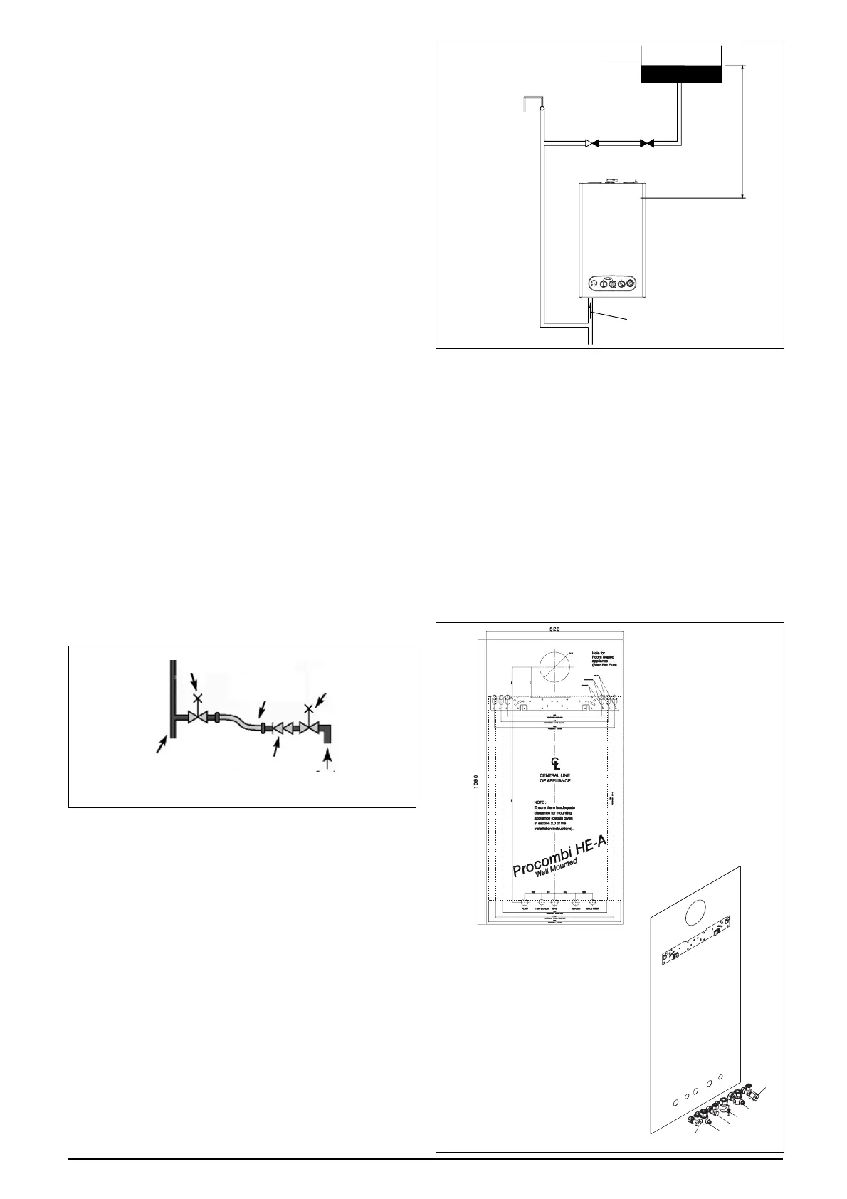
3.6.7 LOW PRESSURE SEALED SYSTEM
An alternative method of filling the system would
be from an independent make-up vessel or tank
mounted in a position at least 1 metre above the
highest point in the system and at least 5 metres
above the boiler (see fig. 6).
The cold feed from the make-up vessel or tank
must be fitted with an approved non-return valve
and stopcock for isolation purposes. The feed pipe
should be connected to the return pipe as close
to the boiler as possible.
3.6.8 FREQUENT FILLING
Frequent filling or venting of the system may be
indicative of a leak. Care should be taken during
the installation of the appliance to ensure all
aspects of the system are capable of withstanding
pressures up to at least 3 bar.
3.7 ELECTRICAL SUPPLY
The appliance is supplied for operation on 230V @
50Hz electrical supply; it must be protected with a
3-amp fuse. The method of connection to the
mains electricity supply must allow for complete
isolation from the supply. The preferred method is
by using a double-pole switch with a contact
separation of at least 3,5mm (3° high-voltage
category). The switch must only supply the appli-
ance and its corresponding controls, i.e. time
clock, room thermostat, etc. Alternatively an un-
switched shuttered socket with a fused 3-pin plug
both complying with BS 1363 is acceptable.
3.8 MOUNTING ON A COMBUSTIBLE SURFACE
If the appliance is to be fitted on a wall of combus-
tible material, a sheet of fireproof material must
protect the wall.
3.9 TIMBER FRAMED BUILDINGS
If the appliance is to be fitted in a timber framed
building, it should be fitted in accordance with the
Institute of Gas Engineers publication (IGE/UP/7)
‘Guide for Gas Installations in Timber Frame
Buildings’.
3.10 INHIBITORS
It is recommend that an inhibitor - suitable for use
with copper and aluminium heat exchangers - is
used to protect the boiler and system from the
effects of corrosion and/or electrolytic action. The
inhibitor must be administered in strict accord-
ance with the manufacturers instructions*.
*Water treatment of the complete heating system
- including the boiler - should be carried out in
accordance with BS 7593 and the Domestic Water
Treatment Association’s (DWTA) code of prac-
tice.
3.11 SHOWERS
If the appliance is intended for use with a shower,
the shower must be thermostatically controlled
and be suitable for use with a combination boiler.
fig.5
Make-up vessel
or tank
Automatic
air-vent
Non-return
valve
Stopcock
5.0 metres minimum
Heating
return
fig.6
flow/return
pipe
control
valve
temporary
connection
control
valve
supply
pipe
double
check valve
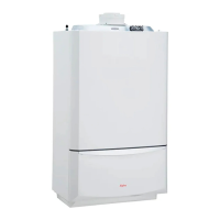
fig. 7
fig. 8
A - safety valve outlet
B - flow
C - DHW outlet
D - gas
E - return
F - DHW inlet
A
B
C
D
E
F