22
These series of checks must be carried out be-
fore attempting any faultfinding procedures on the
appliance. On completion of any task that required
the disconnection and re-connection of any elec-
trical wiring or component, these checks must be
repeated.
7.9 FAULT FINDING
Before attempting any faultfinding, the electrical
checks as detailed in 7.8 must be carried out.
Isolate the appliance from the electrical supply.
Disconnect any external controls from terminal
plug M6 (fig. 16), and insert a link-wire between
the two wires at the ‘TA’ connections (fig. 19).
NOTE
Restore the electrical supply to the boiler and turn
the selector switch to the on position. The boiler
should now function as described in section 7.2.
Should the boiler fail to respond, the internal fuses
and connectors should be checked to ensure
integrity and continuity. If the boiler still fails to
respond, refer to the detailed faultfinding flow-
charts located at the end of this section.
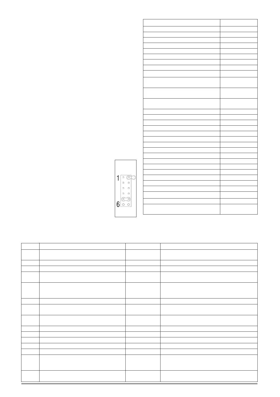
7.10 BOILER CONFIGURATION
The boiler can be configured by means of the
JUMPER Tag which configuration is shown in the
below:
JP4 CONFIGURATION
●●
●●
● JUMPER ON POSITION 1: FLOOR
HEATING (IF SET)/STANDARD
HEATING (IF NOT USED)
●●
●●
● JUMPER ON POSITION 2: (UNUSED)
●●
●●
● JUMPER ON POSITION 3: (UNUSED)
●●
●●
● JUMPER ON POSITION 4: (UNUSED)
●●
●●
● JUMPER ON POSITION 5: COMBI
●●
●●
● JUMPER ON POSITION 6:
(UNUSED)
FOR CONFIGURATION SEE
REFERENCE NUMBER (PIN1 ON
PCB) AS SHOWN IN BELOW.
7.12 COMPONENT VALUES & CHARACTERISTICS
COMPONENT VALUE
Fan 230Vac
Pump 230Vac
Valve actuator (Combi only) 230Vac
Ignition transformer 230Vac
Gas valve 230Vac
Room thermostat connection 230Vac
NTC thermistor (dry contact) 10Kohm
NTC thermistor (wet contact) 10Kohm
FUNCTION VALUE
Standard Heating temperature
range (min – max °C) 40 - 80
Floor Heating temperature
range (min – max °C) 20 - 45
DHW temperature
range (min – max °C) 35 - 60
75% maximum CH time 15 min
Heating OFF hysterisis (°C) SP + 5
Heating ON hysterisis (°C) SP – 5
DHW OFF hysterisis (°C) SP + 5
DHW ON hysterisis (°C) SP + 3
Anti-cycle delay 3-min
Pump over-run 30-sec
Low output (min. output + %) Min+25
CO function max temp. (°C) 95
CO re-light temp. (°C) 75
CO function time 15-min
Flow NTC max temp. (°C) 95
High limit thermostat (°C) 105
Burner thermostat (°C) 170
Maximum differential (°C) 35
IGNITION CONTROL VALUE
Ignition attempts before L/O (lockout) 5
Re-ignition attempts after loss
of flame signal 5
JP4
7.11 FAULT CODES
When the boiler detects a temporary fault condition, the appropriate code is shown flashing on the display. If/when the
fault code is final, the pump will perform a 60-second post circulation and the red LED will be illuminated.
CODE CAUSE ALARM TYPE ACTION
AL10 Ignition failure, flame not sensed, Final Reset, check appliance operation
condense sensor activated
AL20 Limit thermostat fault/fumes thermostat fault Final Reset, check appliance operation
AL21 External device fault (UHT/CPA) Final Reset, check appliance
AL26 Return temperature too high Temporary than Reset, check appliance operation,
final check thermistor
AL28 Temperature differential inverted Temporary than Reset, check pump, ensure there is sufficient
(return sensor temperature higher than final circulation around heating circuit/s
thermistors flowsensor temperature)
AL34 Fan tacho signal fault Final Reset check appliance operation, check fan
AL40 Insufficient system water pressure Final Check/refill system pressure, reset,
check appliance operation
AL41 Insufficient system water pressure Temporary Check/refill system pressure,
check appliance operation
AL52 Internal fault Final Reset, check appliance operation
AL55 Jumper tag fault Final Check jumper tag configuration
AL60 DHW thermistor fault Temporary Check DHW thermistor
AL71 Primary (flow) thermistor fault Temporary Check primary thermistor, check wiring
AL73 Return thermistor fault Temporary Check return thermistor, check wiring
AL74 Over temperature due to Final Reset, check appliance operation, check
low H
2
O pressure pump, ensure there is sufficient circulation
around heating circuit/s
AL79 Flow temperature too high, Temporary than Reset, check appliance operation,
temperature differential too high final check thermistors