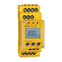
Installation and connection
14
TGH1410en/03.2012
1. DIN rail mounting:
Snap the rear mounting clip of the device into place in such a way that
a safe and tight fit is ensured.
Screw fixing:
Use a tool to move the rear mounting clips (a second mounting clip
required, see ordering information) to a position that it projects
beyond the enclosure. Then fix the device using two M4 screws.
2. Wiring
Connect the device according the wiring diagram.
Ter minal Con nection s
A1, A2
Connection to supply voltage U
s
k, l Connection of measuring current transformers
T / R Connection to the combined test and reset button
11, 12, 14 Alarm relay K1
21, 22, 24 Alarm relay K2
k
l
T/R
11 1412
21 2422
A2A1
T/R
Load

 Loading...