11
8. Install the washer (3) and safety valve (2) in the top
port (discharge port) of the cylinder head (15), then
tighten to a torque of 59 to 66 foot pounds (80-90 Nm).
This port can be identifi ed by the number 2 cast into
the cylinder head.
INSTALLING THE COMPRESSOR
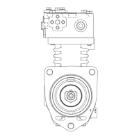
1. Apply a liquid gasket sealant to the compressor / engine
mounting interface (Refer to Figure 3 for compressor
mounting face). Follow the “Engine or Vehicle
Manufacturers guidelines for the proper liquid gasket
sealant material and application procedure.
2. Secure the compressor on the engine mounting
interface using the 6 mounting bolts. NOTE: There
are 2 short bolts and 4 long bolts. Be sure the use the
proper length bolt for the crankcase bolt holes. Run
each of the bolts down fi nger tight, making sure not to
smear the liquid gasket material on the sealing surface.
Once the bolts are all fi nger tight; tighten the mounting
bolts per Engine Manufacturers recommended torquing
sequence and torque requirements.
3. Install any supporting brackets on the compressor in
the same position(s) noted and marked during removal.
4. Inspect all air and coolant lines and fi ttings before
reconnecting them to the compressor. Make certain
o-ring seals are in good or new condition, the threads
are clean and the fi ttings are free of corrosion. Replace
as necessary.
5. Install the discharge and coolant fi ttings, if applicable, in
the same position on the compressor noted and marked
during disassembly. See the Torque Specifi cations for
various fi tting sizes and types of thread at the rear of
this manual. Tighten all hose clamps.
6. Before returning the vehicle to service, perform
the Operation and Leakage Tests specifi ed in this
manual. Pay particular attention to all lines and hoses
disconnected during the maintenance and check for
air, oil, and coolant leaks at compressor connections
and the compressor engine interface. Also check for
noisy operation.
BENDIX
®
360CC SINGLE CYLINDER
COMPRESSOR SPECIFICATIONS
Typical weight . . . . . . . . . . . . 42 LBS (19.1 KG)
Number of cylinders . . . . . . . . . . . . . . . . . . 1
Bore Diameter . . . . . . . . . . . . 3.622 IN (92 MM)
Stroke . . . . . . . . . . . . . . . . 2.126 IN (54 MM)
Calculated displacement at 1250 RPM . . . .15.8 CFM
Flow Capacity @ 1800 RPM & 120 PSI . . . 14.5 CFM
Flow Capacity @ 3000 RPM & 120 PSI . . . .23.1 CFM
Approximate horsepower required:
Loaded 1800 RPM at 120 PSIG . . . . . . . . . 5.2 HP
Loaded 1800 RPM at 0 psig (DLU) . . . . . . . 2.7 HP
Minimum coolant fl ow at maximum RPM . . 2.64 GPM
(10 LPM)
Maximum coolant temperature. . . . . . . 203°F (95°C)
Maximum inlet air temperature . . . . . 122°F (50°C)
Maximum system pressure. . . . . . . . . . . .150 PSI
Minimum oil pressure required . . . . . . . . . 10 PSI
TORQUE SPECIFICATIONS
Assembly Torques
M8x1.25-6g Cylinder Head Bolts. . . . 265-292 In. Lbs.
(30-33 Nm)
M10x1.5 End Cover Bolts . . . . . .195 to 213 In. Lbs.
(22-24 Nm)
M26x1.5 Safety Valve . . . . . . . . . . . 59-66 ft. lbs.
(80-90 Nm) Maximum
M26x1.5 Discharge Port Fittings . . . . . . . 66 ft. lbs.
(90 Nm) Maximum
M16 x 1.5-6H Water Port Fittings . . . . . . 33 ft. lbs.
(45 Nm) Maximum
 Loading...