EasyManua.ls Logo

BENDIX BX2150 AIR COMP-BW1424-

BENDIX BX2150 AIR COMP-BW1424-
36 pages
To Next Page IconTo Next Page
Loading...
1
®
DESCRIPTION
GENERAL
The function of the air compressor is to provide and maintain
air under pressure to operate devices in the air brake and/or
auxiliary air systems.
DESCRIPTION
The BX-2150
compressor is a single cylinder, single stage
reciprocating compressor with a rated displacement of 9.5
cubic feet per minute at 1250 R.P.M. The BX-2150
compressor is constructed from two major assemblies, the
cylinder head and the crankcase. The cylinder head is an
iron casting containing the inlet, discharge and unloader
valving. It is installed on the crankcase and is secured using
four cap screws symmetrically placed. The cylinder head
can be, therefore installed in any one of four different positions
which are 90° apart.
Two governor mounting surfaces, adjacent to the single
rectangular inlet cavity, provide a convenient means of
mounting the governor to the cylinder head. One eighth inch
BX-2150
AIR COMPRESSOR BELT DRIVE MODEL
Bendix
®
BX-2150
Air Compressor
SD-01-331
UNLOADER
STOP
WATER
OUTLET
UNLOADER
PORTS
WATER
OUTLET
AIR OUTLET (2)
(1 NOT SHOWN)
WATER INLET
(NOT SHOWN)
AIR
INLET
AIR INTAKE
INLET VALVE
UNLOADER
PISTON
CONNECTING
ROD
OIL SEAL
PISTON
CRANKSHAFT
ROLLER
BEARING
SLEEVE
BEARING
OIL INLET
REAR END
COVER
AIR OUTLET
DISCHARGE
VALVE
PISTON
RINGS
CRANKSHAFT OIL PASSAGE

Table of Contents

Question and Answer IconNeed help?

Do you have a question about the BENDIX BX2150 AIR COMP-BW1424- and is the answer not in the manual?

BENDIX BX2150 AIR COMP-BW1424- Specifications

General IconGeneral
BrandBENDIX
ModelBX2150 AIR COMP-BW1424-
CategoryAir Compressor
LanguageEnglish

Summary

Bendix BX-2150 Air Compressor

Description

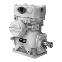
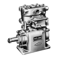
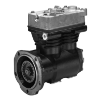
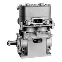
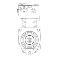
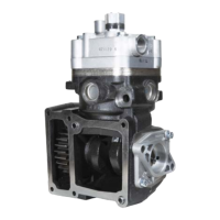
Explains the function of the air compressor in air brake systems.

Operation

Intake and Compression of Air (Loaded)

Details the process of air intake and compression by the piston.

Compressor & The Air Brake System

Lubrication

Cooling

Air Induction

Preventative Maintenance

Inspection of Parts

Assembly

Crankcase & Crankshaft Assembly

Instructions for assembling the crankcase and crankshaft.

Compressor Troubleshooting

WARNING! PLEASE READ AND FOLLOW THESE INSTRUCTIONS TO AVOID PERSONAL INJURY OR DEATH:

Compressor Removal & Disassembly

Cylinder Head Disassembly

Detailed instructions for disassembling the cylinder head.

Compressor Crankcase Disassembly

Instructions for disassembling the compressor crankcase.

Piston & Connecting Rod Assembly

Final Compressor Assembly

Testing Rebuilt Compressor

Introduction to the Air Brake Charging System

Table A: Maintenance Schedule and Usage Guidelines

Air Brake Charging System Troubleshooting

Symptom: 2.0 Oil on the Outside of the Compressor

Addresses oil leaks at compressor/engine connections and from the compressor.

Symptom: 4.0 Oil in Supply or Service Reservoir (air dryer installed)

Discusses maintenance, duty cycle, and temperature issues related to oil in reservoirs.

Symptom: 4.0 Oil in Supply or Service Reservoir (continued)

Addresses poorly filtered inlet air, compressor malfunction, and oil at valves.

Symptom: 9.0 Air Brake Charging System Seems Slow to Build Pressure.

Covers normal function, leakage, undersized compressor, unloader, and head gasket issues.

Symptom: 9.0 Air Brake Charging System Seems Slow to Build Pressure. (continued)

Addresses restricted discharge/inlet lines, poor inlet air, and compressor malfunction.

Symptom: 10.0 Air Charging System Doesnt Build Air.

Lists causes like governor, discharge line, air dryer heater, and compressor malfunctions.

Symptom: 11.0 Compressor Safety Valve Releases Air (Compressor Builds Too Much Air).

Explains how restricted discharge lines cause over-pressurization.

Symptom: 12.0 Air Dryer Safety Valve Releases Air.

Discusses causes for the air dryer safety valve releasing air.

Symptom: 13.0 Reservoir Safety Valve Releases Air

Addresses reservoir safety valve releasing air.

Symptom: 16.0 Compressor Leaks Air

Addresses air leaks at connections, unloader malfunction, and head gasket damage.

WARNING! Please READ and follow these instructions to avoid personal injury or death:

Tests

Test 2: Air Brake System and Accessory Leakage

Method to test for air leaks in the system and accessories.

Test 3: Air Compressor Discharge Temperature and Air Dryer Inlet Temperature

Procedure to measure compressor and air dryer inlet temperatures.

Tests (continued)

Appendix A: Information about the BASIC Test Kit (Bendix PN 5013711)

Appendix A continued: Information about the BASIC Test Kit (Bendix PN 5013711)

Related product manuals