Do you have a question about the BENDIX TU-FLO 700 COMPRESSOR and is the answer not in the manual?
Inspects crankshaft surfaces, journals, and oil passages for wear or damage.
Provides steps and torque specifications for installing the crankshaft.
Describes the assembly of pistons, connecting rods, and wrist pins.
Identifies potential internal compressor leaks causing oil to appear externally.
Addresses high temperatures as a cause for oil passing into the air system.
Links high duty cycles to potential oil in reservoirs due to compressor strain.
Identifies restricted discharge lines as a cause for slow air build-up.
Covers restricted air inlet lines impacting compressor performance.
Points to compressor malfunction as a cause for slow pressure build-up.
Explains potential reasons for coolant leaks from the compressor.
Discusses causes for a noisy compressor, specifically for multi-cylinder units.
Provides information and instructions for using the Bendix BASIC Test Kit.
Provides recommendations for discharge line installation and length for cold weather.
| Brand | BENDIX |
|---|---|
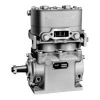
| Model | TU-FLO 700 COMPRESSOR |
| Category | Air Compressor |
| Language | English |