DESCRIPTION
The function of the air compressor is to provide and
maintain air under pressure to operate devices in air brake
systems. The Bendix
®
360cc compressor is a single-
cylinder compressor with a rated displacement of 15.8 cubic
feet per minute at 1250 RPM. The compressor consists
of an integral water-cooled cylinder head assembly and
water-cooled crankcase.
The cylinder head assembly is made up of an aluminum
cylinder head, an aluminum cooling plate, and a steel valve
plate assembly with two sealing gaskets. The cylinder head
contains air and water ports. The cooling plate, situated
between the head and valve plate, assists in cooling the
head assembly. The valve plate assembly, consisting of
brazed steel plates, has separate valve openings and
passages to allow air and coolant to fl ow in and out of the
compressor. See Figure 1 for an external view, and Figure
3 for an exploded view
.
The compressor is equipped with a safety valve in the
cylinder head safety valve port, directly connected to the
discharge port. The safety valve protects the compressor
head in the event of excessively high discharge line
pressure, for example, in the event of blockage downstream
of the compressor. Excessive air pressure causes the
safety valve to unseat, releases air pressure and gives an
audible alert to the operator.
The compressor is cooled by air fl ow, as well as by engine
coolant. The engine coolant fi rst enters the crankcase
water jacket to cool the cylinder bore, then passes through
passages in the valve plate assembly, cooling plate, and
cylinder head and then out of a port at the top of the
compressor, back to the engine.
A nameplate is attached to a fl at cast face on the side of
the crankcase. It is stamped with information identifying
the compressor designation, customer piece number,
compressor assembly part number and serial number.
See Figure 2
.
GENERAL INFORMATION
This Bendix
®
360cc compressor is a “discharge line
unloader” (DLU)-style compressor, meaning that the
compressor pumps continuously, unlike some compressor
designs which use an "unloader" mechanism in the
compressor head to switch from a pumping mode to a
non-pumping mode. Instead, the control of air delivery to
the vehicle’s air system is managed by using a separate
discharge line unloader valve mounted in parallel with a
turbo cut-off style of air dryer (see Figure 6).
SD-01-3121
BENDIX
®
360CC SINGLE CYLINDER COMPRESSOR FOR
INTERNATIONAL MAXXFORCE
™
11 AND 13 BIG BORE ENGINES
MAXXFORCE
™
is a trademark of International Engine Intellectual Property Company, LLC.
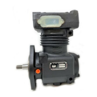
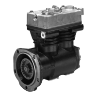
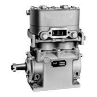
FIGURE 1 - BENDIX
®
360cc SINGLE CYLINDER
COMPRESSOR
FIGURE 2 - NAMEPLATES (TWO STYLES)
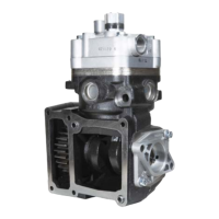
Safety
Valve
Cooling
Plate
Valve Plate
Assembly
Cylinder
Head
Crankcase
Coolant
Enters Here
Locating
Pins
Coolant Exits at
Top of Head
(See Figure 7)
Bendix Part Number . . . . . . A
Customer Piece Number . . . . B
Compressor Serial Number . . C
A
B
C
A
B
C