3
NON-COMPRESSION OF AIR (UNLOADED)
COMPRESSOR AND AIR DRYER SYSTEM
(REFER TO FIGURE 6)
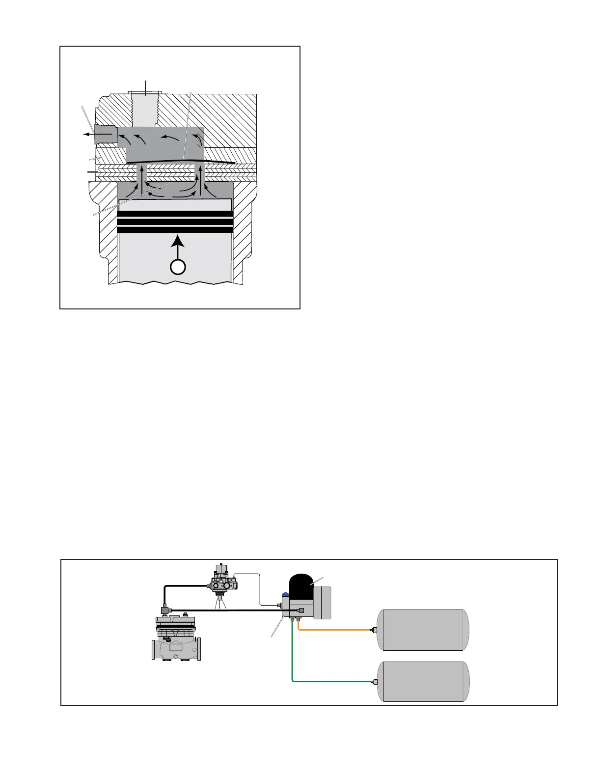
Air delivery to the vehicle’s air system is controlled by the
governor and the air dryer, or with a separate discharge line
unloader valve. The governor is plumbed to the component
(e.g. air dryer or DLU valve) in order to control when the
air is delivered to the vehicle’s air system.
When air pressure in the supply reservoir reaches the
cutout setting of the governor, the governor delivers
system air to the discharge line unloader-style (DLU) air
dryer’s control port. This allows the discharge air from the
compressor to fl ow out the exhaust port of the air dryer.
Note: The Bendix
®
360cc compressor is a discharge line
unloader-style unit. This means that the compressor
functions in a continuous pumping mode regardless
whether the brake system requires air. It requires a
downstream device (e.g. turbo cut-off style air dryer and
discharge line unloader valve) to unload the system when
the air system has suffi cient stored compressed air.
LUBRICATION
The vehicle’s engine provides a continuous supply of oil
to the compressor. Oil is routed from the engine to the
compressor’s oil inlet. Note: There is no external oil supply
line; the oil delivery is located at the engine to compressor
mounting face. This pressurized oil fl ows to the precision
front sleeve main bearing, and via an oil passage in the
crankshaft routes pressurized oil to the connecting rod
bearings and the rear journal associated with the end cover.
Spray lubrication of the cylinder bore and connecting rod
wrist pin bushing is obtained as oil is forced out around the
crankshaft journals by engine oil pressure. Oil then falls to
the bottom of the compressor crankcase and is returned
to the engine through the opening at the compressor
mounting fl ange.
COOLING
The Bendix
®
360cc Single Cylinder Compressor is cooled
by air fl owing through the engine compartment as it passes
the compressor’s cast-in cooling fi ns and by the fl ow of
engine coolant through the cylinder head assembly and
the water jacket around the cylinder bore of the crankcase.
Coolant supplied by the engine cooling system passes
through connecting lines into the cylinder head, cooling
plate, valve plate assembly, into the crankcase water
jacket and returns through the same components, out of
the coolant outlet port of the cylinder head and returns to
the engine. Figure 7 illustrates the approved coolant fl ow
connections. Proper cooling is important in minimizing
discharge air temperatures – see the tabulated technical
data on page 11 of this manual for specifi c requirements.
Compressor
Governor
Air Dryer
FIGURE 6 - TYPICAL BENDIX
®
360 (DLU) COMPRESSOR AIR CHARGING SYSTEM
Front Service
Reservoir
Rear Service
Reservoir
DLU Valve
FIGURE 5 - OPERATION - COMPRESSION
Piston Moving Up
Air Inlet
Port
Inlet
Valve
Closed
Air
Discharge
Port
Discharge
Valve
Open
Valve
Plate
Cooling
Plate
 Loading...