20
Silver Crown Plus Pilot’s Guide
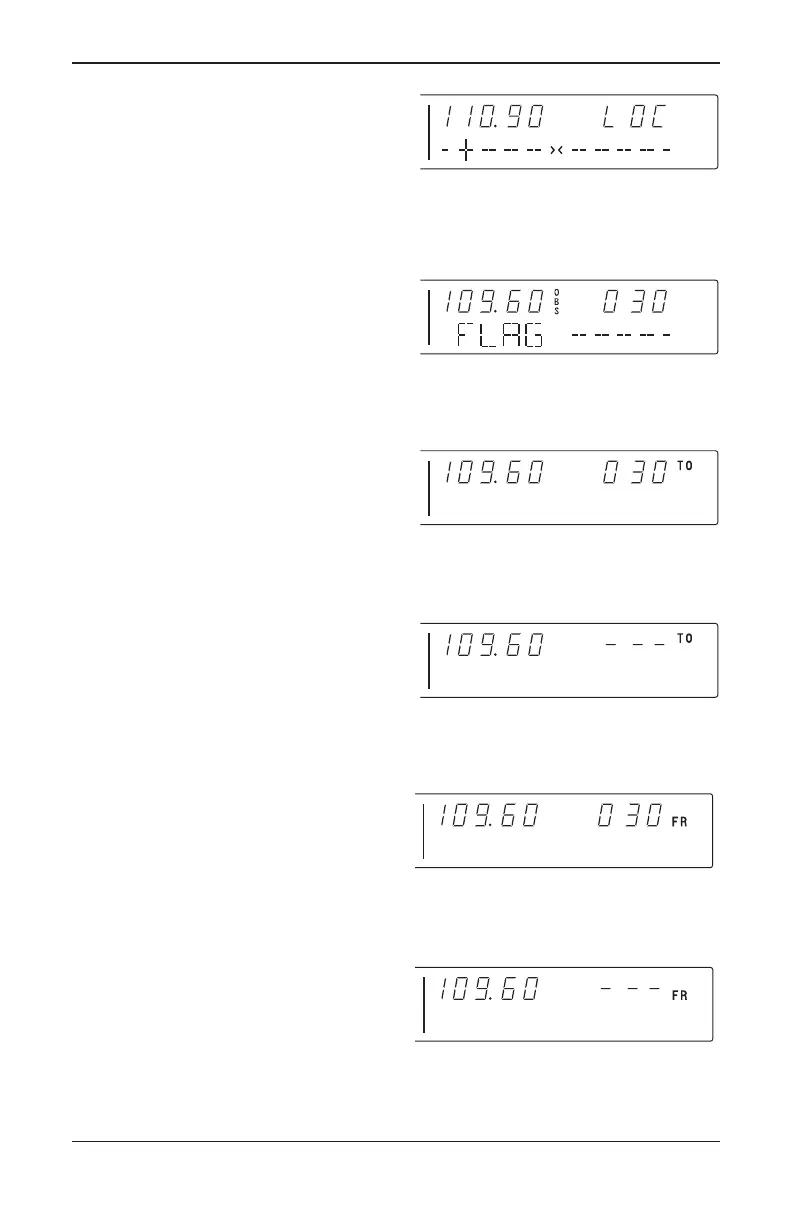
When the ACTIVE window is tuned to a
localizer frequency, the standby frequen-
cy area is replaced by “LOC” (Figure 12).
When the received signal is too weak
to ensure accuracy the display will “flag”.
See Figure 13.
Depressing the mode button will
cause the NAV display to go from the
ACTIVE/CDI format to the
ACTIVE/BEARING format. In the BEAR-
ING mode, the increment/decrement
knob channels the ACTIVE frequency
window and depressing the frequency
transfer button will cause the ACTIVE fre-
quency to be placed in blind storage and
the STANDBY frequency (in blind stor-
age) to be displayed in the ACTIVE win-
dow display. In bearing mode of opera-
tion, the right hand window of NAV dis-
play shows the bearing TO the station.
Figure 14 illustrates the NAV side of
the display in this mode.
When a too weak or invalid VOR sig-
nal is received the display flags as shown
in Figure 15.
Another push of the mode button will
cause the NAV display to go from the
ACTIVE/BEARING format to the
ACTIVE/RADIAL format as shown in
Figure 16. In the RADIAL mode, the
increment/decrement knob channels the
ACTIVE frequency window and depress-
ing the frequency transfer button will
cause the ACTIVE frequency to be
placed in blind storage and the STANDBY
frequency (in blind storage) to be dis-
played in the ACTIVE window display. In
radial mode of operation, the right hand
window of NAV display shows the radial
FROM the station. Figure 16 illustrates
the NAV side of the display in this mode:
When a too weak or invalid VOR sig-
nal is received the display flags as shown
in Figure 17.
FIGURE 17
VOR mode
active/radial flag display
FIGURE 12
Nav display Active localizer frequency/
CDI format
FIGURE 13
VOR flag display
FIGURE 14
VOR mode bearing to function
FIGURE 15
VOR mode active/bearing,
flag display
FIGURE 16
VOR mode
radial from function
Silver Crown Plus 5/12/00 9:55 AM Page 20