SP-7XE/F Full-Rise Scissor Lift 17 P/N 5900010 — Rev. B3 — September 2023
consult with your Concrete Specialist to determine the size, depth, and location of the conduits
needed for the Hydraulic and Air Lines. No Lift Anchor Bolt should be closer than 6-inches to any
inconsistency in the concrete (e.g., expansion joints or cracks).
⚠ WARNING Do not install the Lift on a surface with a slope greater than 3°. A slope in excess of
3° could lead to an unstable vehicle resulting falling and resulting in property
damage, personal injury, or death.
• SP-7XEF installations. BendPak strongly recommends early consultation with a Concrete
Specialist to plan and create the Concrete Cutouts for your Flush-Mount Lift.
• Power. The Lift requires a 208 to 240 VAC, single phase power source available near the
Console. If electrical power is to be run to the Console under New Pour Concrete, consult with a
licensed Electrician to ensure the correct location, depth, size, and type of electrical conduit are
installed according to national and local electrical codes.
• Operating temperature. The Lift is designed to be used between temperatures of 41º to 104ºF
(5º to 40ºC).
• Outdoor installation. The SP-7XE/XEF Lifts are designed and approved for indoor installation
and use only. Outdoor installation is prohibited.
• Second floor installations. Do not install the Lift on a second floor or elevated floor without
first consulting the building architect and receiving approval.
• Set up Chalk Line Guides. Create Chalk Line Guides or tape lines to verify the Lift will function
in your chosen location. BendPak strongly suggests a dry run using a vehicle to verify the Lift
approach and exit will be safe and efficient in this location.
Create a Floor Plan
Make sure to plan out, in advance, where the Lift and Console will be installed:
• Clearance. Verify there is adequate clearance on all sides and above the Lift.
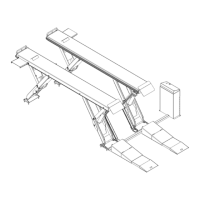
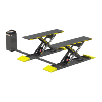
• Console. The Console must be near the Lift; it can be installed on either side of the Lift, but only
on the Cylinder-end of the Platforms. The supplied Hydraulic Hoses can support up to 40 inches
between the Lift and the Console.
• Operator. The Operator at the Console must have a full, unobstructed view of the Lift while
raising and lowering vehicles.
• Power. The Console must be positioned near an appropriate power source.
• Create Chalk Lines. Create Chalk Lines or tape lines for the Lift to verify it is properly aligned in
the location.