SP-7XE/F Full-Rise Scissor Lift 20 P/N 5900010 — Rev. B3 — September 2023
Prepare the Concrete Cutouts: SP-7XEF Only
Important: BendPak strongly recommends working with a Concrete Specialist to plan and create
the Concrete Cutouts for your Flush-Mount Lift.
It is important to understand the following before creating the Concrete Cutouts for your Lift:
• Planning ahead. Before creating Concrete Cutouts for the Lift, decide where the Lift is to be
installed, which side of the Lift will the Console be installed on, how far away from the Lift will the
Console be, and how far apart the two Bases will be. These decisions need to be incorporated into
the plan created with your Concrete Specialist.
• Concrete Cutouts. The Lift Bases of a Flush-Mount Lift are installed in a recessed section of the
floor, called a Concrete Cutout. This cutout may be made in the existing concrete if it meets the
thickness, compression, and condition requirements listed in this section. If not, then a reinforced
New Pour is required.
• Depth of the Concrete Cutouts. Concrete Cutouts must be a specific depth below floor level
so that when the Lift is put down into the Concrete Cutout, the top of the Lift’s Platforms are flush
with the existing floor.
• Concrete Curing Time. New Concrete Pour must cure for a minimum of 28 days before they
are strong enough to support Anchor Bolts.
• Floor Material. Concrete Cutouts and New Pour must be surrounded by and created in a
Concrete floor; no other surface (asphalt, dirt, anything else) is acceptable.
• Cutout Size. Concrete Cutouts need to be slightly larger than the Bases. The values listed at the
end of this section add 0.5 inch / 2.75 mm on all four sides to the Length and Width of the
Bases.
• Concrete Depth. The Concrete depth below the bottom of the Concrete Cutouts must be
deep enough for the Anchor Bolts; a minimum of 4.25 in. / 108 mm is required.
• Air and Hydraulic Lines: Your plans for the Concrete Cutouts must account for how these Air
and Hydraulic Lines will be routed to the Console.
PVC Conduit with a 2.5-inch minimum diameter is commonly used to route the Hydraulic and Air
Lines between the two Frame Assemblies and the Console. If you plan to cut in existing concrete,
then plan for cutting channels between the Frame Assemblies and the Console to fit the PVC
Conduit and then cover with Concrete.
Both Bases include rectangular openings for routing the Hydraulic and Air Lines already created;
there are two per Base, both on the Cylinder end. These opening are available they are not
required to be used.
• Lift Location. Use care when selecting a location for a Flush-Mount Lift. Once you create your
Concrete Cutouts, the Lift location is permanent. Choose a location that allows a straight approach
to the Lift, without obstructions, and allows access to air and the power source.
• Console Location. The Console can go on either side of the Lift, but at the Cylinder end of the
Frame Assemblies. The supplied Hydraulic Hoses support up to 40 inches / 1,016 mm away from
the closest Frame Assembly. You can mount the Console farther away, but this will require
custom–length Hydraulic Hoses, longer Air Lines and more Hydraulic Fluid. Remember to create a
path through the Concrete towards the Console for routing the Hydraulic and Air Lines.
• Distance between Bases. The Bases can be a variable distance apart, allowing you to pick
the best width for the Vehicles you will be lifting.
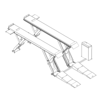
• Diagram. Use the dimensions shown in the following diagram as a guide for your Concrete
Cutouts.
 Loading...